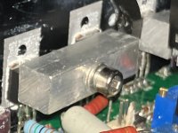
The case would be pressed against a vertical heat sink using a bar and insulated by a SIL-Pad. Thinking the leads can actually be wires instead of to-220 leads to reduce mechanical stress on the solder connection (weakest link?) between the TO-263 tabs and wires.
Attachments
Never checked those but would be very surprised at center leg not being connected.
They save nothing by doing so and on the contrary somebody might hardwire it.
Footprint may reflect oven and reflow soldering use, and yet ..,
That said, multimeter testing rules.
Please test and post results.
They save nothing by doing so and on the contrary somebody might hardwire it.
Footprint may reflect oven and reflow soldering use, and yet ..,
That said, multimeter testing rules.
Please test and post results.
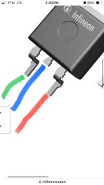
The tab and centre leg are the leadframe substrate layer. The different package styles vary by how the lead-frame is cropped and formed, same leadframe to start with I think.
Leadframes are first stamped out with all the pins connected by a ring of metal, then they get the chip attached and wire-bonded, then the epoxy is moulded around it, then the ring that shorts all the pins together is cut out with another die (i.e. after the epoxy body can support the pins) and the pins formed/trimmed.
Leadframes are first stamped out with all the pins connected by a ring of metal, then they get the chip attached and wire-bonded, then the epoxy is moulded around it, then the ring that shorts all the pins together is cut out with another die (i.e. after the epoxy body can support the pins) and the pins formed/trimmed.
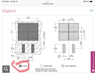
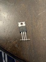
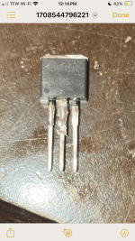
It looks like 22 gauge is the closest match to the TO-220 leads (~.35mm^2 area).
https://www.infineon.com/cms/en/product/packages/PG-TO220/PG-TO220-3-1/
I am using 22 AWG headers to provide a kind of cast for the solder. As it turns out these fit snuggly with the leads") .
.
https://www.mouser.com/ProductDetail/538-560124-0101-CT
Will update with photos soon.
https://www.infineon.com/cms/en/product/packages/PG-TO220/PG-TO220-3-1/
I am using 22 AWG headers to provide a kind of cast for the solder. As it turns out these fit snuggly with the leads
.https://www.mouser.com/ProductDetail/538-560124-0101-CT
Will update with photos soon.
Last edited:
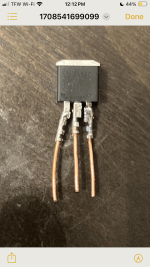
Here’s versions 1 and 2. Version 1 with 22 awg solid wire seems crammed and runs the risk of shorting (maybe) with heat. In version 2 leads were removed from a TO-220 package. I think this is the best solution. Planning to finish the full set later this week with this quick disconnect terminal (w/ just the tab housing) to secure the center lead. There should be enough clearance to fit the center lead over/under the TO-220 lead. The outside leads have much plenty of surface area for soldering without a terminal. I’ve attached photos of versions 1 and 2, and how I secured the leads for the transplant from TO-220 to TO-263. This will work! But for how long?! The center lead is only 1.5mm…
Attachments
Last edited:
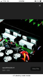
So far so good after a few hours of music. The quick disconnect terminal was too small. I ended up using the molex interconnect. The motivation behind this work was restoring the creek destiny to its factory specs (huf76639). The alternate irl2910 (some distortion at idle voltage - too much edge) and irl540n (too laid back less punch in bass) proved lacking ime.
- Home
- Design & Build
- Construction Tips
- Package converting - TO-263 to TO-220?