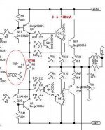
This is the emitter resistor for the current sink, wich defines the current flow there. With 180R the current will be about 8.5mA, this means more than 4mA per device....this is TOO much !fotios said:3) Play a little with the value of R7 from 560R down to 180R with different values.
kalmara said:
This is the emitter resistor for the current sink, wich defines the current flow there. With 180R the current will be about 8.5mA, this means more than 4mA per device....this is TOO much !
You count with Voltage 1.53 V across resistor.
With a normal RED LED we get ~ 1 Volt.
Because there is one B-E drop (~0.65 V) to subtract from LED Vf.
If you use e.g GREEN LED or other than 'normal red', then you may get a bit higher voltage.
But recomendation is:
Use normal (1.6.1.8 V) RED LED
This will make better temperature compensation than GREEN LED, and so keep current at fairly constant level.
RED LED is also low noise voltage reference, compared to for example zenerdiode.
fotios example for resitor values, with 180R min value,
gives something like 2.8 mA per transistor
lineup
") regards
regardsSakis,
I've found that the master transistor of a CFP should be fast, around 70MHz or so, while the slave transistor should be slow, around 15-30MHz. Otherwise, capacitors should be placed across base/collector of the master device to prevent oscillations.
These are the changes I would make:
1. Reduce R13 and R14 to 100R for 6.5mA nominal master Ic.
2. Replace Q5 and Q6 with smaller, faster TO126 devices with heatsinks. Typically they will each dissipate 360mW.
3. Replace Q7 and Q8 with slower devices, such as the MJE15032/31 devices you are using. Heatsink well.
4. Replace R16 and R17 with one resistor, strung across the output outputs of each CFP but not connected to the output rail. This should be around 18R half watt for 70mA through the CFPs.
5. Place a high quality film cap of 1uF across the 18R resistor.
6. Use 4.7R base stopper resistors on the output devices.
This output stage is very similar to Roender's amp; and should mimic the drive circuit. CFPs have great speed, terrific linearity, but at switch off they are very unstable. Best to keep them on at all times.....
This should prevent the CFP oscillating. It's only one side which is oscillating; we are close to stability now.
Hope this helps,
Cheers,
Hugh
kalmara said:
This is the emitter resistor for the current sink, wich defines the current flow there. With 180R the current will be about 8.5mA, this means more than 4mA per device....this is TOO much !
Hi neighbor
First from the 8,5mA you wrote, i can suppose that the voltage drop accross the LED it is about 1,53V. How you calculated this value of Vdrop? Please inform me because i don't know nothing about this. The only that i know it is the stable current flow of a LED under any temperature variaton. It is by alone thermally compensated.
As for the resistor value i don't mean a direct replacement with a 180R (maybe i was not clear in my phrase) but a series of tests by gradual reducing the value of R7 down to 180R.
For the record, in my projects i use a value of 6mA to feed the LTP so as i can obtain the smallest as possible rise time of signal during the positive slewing. But Sakis may experimented for this with the use of square waves of 10KHz in input and not sine waves.
I remembered that, before 15 years, when i used the same about input topology as in this ESP project, in my circuit used the following with success:
1) Instead a led i used two 1N4002 in series between the b-e junction of Q1. The R7 was either 270R for +/-56V supply (thus the current for LTP was 1,4V / 270 = 5,1mA) or 180R for+/-68V supply (thus a current of 8mA for LTP).
2) R5 was always 680R
3) R6 don't used
4) Between the +V supply rail and the emiter of Q4 there was a 47R resistor.
I believe Sakis may experimented with all these above by using square waves for a clear view of variations resulted step by step.
Also i think that for his attempt to increase the number of output devices, the fixed Iq it is inadequate and may increased.
Regards
Fotios
Lineup, please, do not argue - I've asked myself about that ! The answer was :

I think your calculations are wrong ... the 1N4002 drop about 0.7V in forward flow, but you do not use this voltage for the current calculations, furst you substract the Vbe drop of the transistor (about 0.65V), wich means 1.4V - 0.65V = 0.75V / 270R = 2.7mA. The result is identical to the one, quoted first in the green led example and 560ohms emitter resistor - about 1.35 per LTP leg.
And why use the RED one ? Rod Elliott reccomends GREEN one not for an accidentally reason...I don't know about you, but I trust the man.Kingbrite state the Vf typ of a standard green LED as 2.2v. So 2.2-0.65/560=0.0027. So that gives 1.35ma per LTP leg.
Hello to you too, neighbour.1) Instead a led i used two 1N4002 in series between the b-e junction of Q1. The R7 was either 270R for +/-56V supply (thus the current for LTP was 1,4V / 270 = 5,1mA) or 180R for+/-68V supply (thus a current of 8mA for LTP).
I think your calculations are wrong ... the 1N4002 drop about 0.7V in forward flow, but you do not use this voltage for the current calculations, furst you substract the Vbe drop of the transistor (about 0.65V), wich means 1.4V - 0.65V = 0.75V / 270R = 2.7mA. The result is identical to the one, quoted first in the green led example and 560ohms emitter resistor - about 1.35 per LTP leg.
kalmara said:Lineup, please, do not argue - I've asked myself about that ! The answer was :
And why use the RED one ? Rod Elliott reccomends GREEN one not for an accidentally reason...I don't know about you, but I trust the man.
Hello to you too, neighbour.
I think your calculations are wrong ... the 1N4002 drop about 0.7V in forward flow, but you do not use this voltage for the current calculations, furst you substract the Vbe drop of the transistor (about 0.65V), wich means 1.4V - 0.65V = 0.75V / 270R = 2.7mA. The result is identical to the one, quoted first in the green led example and 560ohms emitter resistor - about 1.35 per LTP leg.
As i remembered the practical measurement of Vdrop accross the 270R resistor was about 1,3V always. I don't speak for theoretical but for practical results.
Regards
Fotios
aksa ....fotios ...line up .....
once more i am speachless in front of the forum thank you people all so much i will moove arround all these suggestions and will post all my testings arround next week ( iam very busy with a lot of rendals this weekend )
though there is one question i have to ask
why should i mess up with a design that allready working problem free and try to make improovments that i am not sure if i am able to evaluate .
i belive that the problem originally oqured by changing the output devices from mjw1302 to mj 15003 otherwiswe the allthing is working with in specs
rod says that this is a sub amplifier working almost in class b and dont expect miracles in high frequency ....
i will make a set and follow most of these advices and see if i can get measurable changes ..... otherwise my intention is to keep it as is ......
the only thing i am pretty shure about that is idle since rail voltage is kind of low but testings up to 70volts will follow and also a version with 8 transistors per amp ( mj150025 and pair ) with rails 80+80 volt is also on the way which is also the one that interest me at the most
Re: aksa ....fotios ...line up .....
A very intelligent question, sakis!
I say you should change as little as possible.
Mr. Elliott (ESP) from Australia knows much more than 99% of all people around here.
Inlcuding me, Mr. Lineup.
And especially about his own circuits ....
You can listen to people good suggestions.
Put all those advices into your head, your memory MegaBytes.
One day you can have good use for these ideas in another amplifier.
But TRUST Mr. Elliott ESP Projects webpages, please.
Whatever bad thinking he has published, he will remove from his articles,
if they are not good.
Finally, if we would follow all advice from 10 different people, when build amplifier,
we would not get something good.
Shortly, it would be like you say it: A mess
lineup tells his opinion, on changing an original & good design
sakis said:once more i am speachless in front of the forum
thank you people all so much
though, there is one question i have to ask:
why should i mess up with a design that allready working problem free
and try to make improvements
A very intelligent question, sakis!I say you should change as little as possible.
Mr. Elliott (ESP) from Australia knows much more than 99% of all people around here.
Inlcuding me, Mr. Lineup.
And especially about his own circuits ....
You can listen to people good suggestions.
Put all those advices into your head, your memory MegaBytes.
One day you can have good use for these ideas in another amplifier.
But TRUST Mr. Elliott ESP Projects webpages, please.
Whatever bad thinking he has published, he will remove from his articles,
if they are not good.
Finally, if we would follow all advice from 10 different people, when build amplifier,
we would not get something good.
Shortly, it would be like you say it: A mess
lineup
tells his opinion, on changing an original & good designthanks line up
i still belive that in any amp there is room for changes aiming for the best ..... but the best is very subjective .... depends an the way you look at it .....
will stay close to the original design and let you know ......
allready i feel kind of guilty messing up with somebody else's design but lets see ...... may be something good comes out of this .....
( small input : the blody thing runs virtually cold !!!!!!!!!!!!! at least in such rail voltage and even resistive loads of 4 ohm)
here is a picture
An externally hosted image should be here but it was not working when we last tested it.
Re: thanks line up
Do not feel anything 'guilty'. It is your life, your project.
As long as you get a result that makes you happy, go ahead!
Most of us here around take some good or bad designs
and make them better or not so good as original
All the time!
If you have some questions about ESP Project 68
or anything you like to know, you should first go to 'the man himself'.
I do not know how often he has time to visit his forum,
but over there are helpers that are SPECIALISTs on ESP Sound Projects:
http://www.sound.westhost.com/phpBB2/index.php
Nice photo, nice amplifier, sakis
regards, lineup
sakis said:
allready i feel kind of guilty messing up with somebody else's design but lets see
...... may be something good comes out of this .....
Do not feel anything 'guilty'. It is your life, your project.
As long as you get a result that makes you happy, go ahead!
Most of us here around take some good or bad designs
and make them better or not so good as original
All the time!
If you have some questions about ESP Project 68
or anything you like to know, you should first go to 'the man himself'.
I do not know how often he has time to visit his forum,
but over there are helpers that are SPECIALISTs on ESP Sound Projects:
http://www.sound.westhost.com/phpBB2/index.php
Nice photo, nice amplifier, sakis regards, lineup
i know that ...line up
but i also now that rod is way to busy to bother with my mods ....this will be my last thing to do .....
play with higher rail voltage, follow some advice ,one step at the time and slowlly ...these ar the things i am going to do
also given as a fact i know very well what to expect from this amp ....so lets see
thank you so much people !!!!!!!!!!!!!!!!!!!!!!!!!!!
Re: i know that ...line up
yes, you do that.
then you post again, to keep us informed
see you later
sakis said:play with higher rail voltage,
follow some advice, one step at the time and slowlly
...these ar the things i am going to do
yes, you do that.
then you post again, to keep us informed
see you later
Rahkik, this thread is 8 years old and the best place to ask about problems with ESP designs is at the ESP forum because some relevant details of Rod's designs, including any previous versions, are only given to purchasers of his PCBs.
Generally, any DC coupled amplifier should have close to zero DC or AC at the the output when idle with no input signal. With an audio input signal, it obviously must change according to the audio signal - amplified to a peak-to-peak voltage up to almost as much as the full rail-to-rail supply voltage. Is your query about a DC voltage there that should not be or you are you just curious to know how much voltage equates to 540W/4R?
Quoting from Rod's P68 article on the ESP website, regarding the power supply:
"The total DC is over 110V (or as much as 140V DC!), and can kill you."
The maximum safe output (AC) voltage at clipping that the amplifier can deliver will be a little less at perhaps 130V peak, depending on load and whether the power transformer used is correct as specified, its regulation is good and the power transistors are correct too.
If you read the article, you'll see that the specification for 540W/4R requires 2VRMS input for full peak power with the correct number of On-Semi MJL4281/4302 devices. If you build it for 300W with the original number of devices shown in the images, you should not use it with 4R loads and the same high voltage supply. Use a 110V rail-rail voltage supplies instead, as shown in the alternative figures and comments.
Amplifiers have fixed amplification ratios, meaning the output can only be made variable from OV to the maximum, by the volume setting and signal program from the preamplifier it is connected to, such as a special subwoofer control preamp like P48 or one that may already be fitted in a HT receiver.
Last edited:
- Status
- This old topic is closed. If you want to reopen this topic, contact a moderator using the "Report Post" button.
- Home
- Amplifiers
- Solid State
- p68 trouble .....