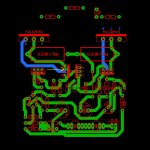
Absolutely, make sure they are in thermal contact and that the TO-126 back plates (collectors) are not in electrical contact.Isn't it enough for Q5 to contact Q9 to do the thermal compensation?
You can easily rotate Q9 180° to avoid that and connect its missing base link.
Last edited:
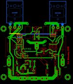
I understand, in this case i thought about thermally joining Q5 and Q9, the thermal exchange will be more efficient joining the two only with mica. Jumper to connect the base.Absolutely, make sure they are in thermal contact and that the TO-126 back plates (collectors) are not in electrical contact.
You can easily rotate Q9 180° to avoid that and connect its missing base link.

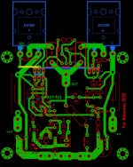
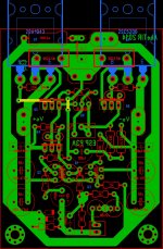
MJF .Tell me my friend which version you want me to send you-Lay 6. Just give me your email ....
BR Nikos.
BR Nikos.
Attachments

Hello..
I'm building the p3a, and I have a question regarding power supply voltages.
I've seen lots of posts wanting higher rail power than +/÷35 volt, I on the other
Hand want to run it from +/÷ 27 volt, it's a tad lover than adviced by Rod elliot,
Should I lower resistors in input current sources, or just leave it as is..?
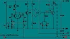
I have another question, regarding the speaker protection board I'm using.
It puzzles me that it does not need any ground reference, as pictures show it uses four relays, two are in parallel for lower resistance, one channel is speaker in and one out.
The ground shown in schematic is it's own power supply, +/÷ 12 volt and the center.
So how does it determine eventual DC if it has no reference?
Attachments
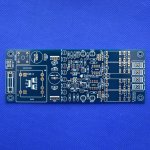
That's also my thought, but if you look at pcb, there is no terminal on pcb.
Its bought from a "reliable" vendor.
So the solution is to hook up a wire from pcb ground to amp psu ground ?
My construction is dual mono, and this might create ground loops, I aimed for 10r ground lift,
And input grounds tighed together, might be asking for trouble, I followed hifisonix pdf on dual mono wiring
Power supply question.
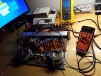
I build the p3a with good original parts, and this is as far as I can take it right now, but how about psu?
How critical is psu ripple? .
I tried different bias levels, 500mv bias produced 15mv ripple on psu, 100mv produced 5mv.
Psu (one side) 20v 300w toroid. Single rectifier bridge with 100nf across ac. 6 10000uf 63v roederstein.
Between each capacitor I placed a 0R2 resistor, and 0R2 between rectifier and first cap, to minimize charge current spikes.
Any ideas for further improvement before the lid comes on..?
Attachments
This is very serious psu. Mine is simple as hell. Bridge>two industrial 12000uf caps, no smoothing resistors or anything...
I tried bypass caps for bridge while experimenting. Different values..
It makes amp sounds thin!
So I removed them.
No speaker protection or anything..
I tried bypass caps for bridge while experimenting. Different values..
It makes amp sounds thin!
So I removed them.
No speaker protection or anything..
I had all the parts laying around collecting dust anyway.
Wish I had courage like you and skip speaker protection, I was thinking about a crowbar protection that blow rail fuses, might use that solution later on.
Tomorrow I will hook up both channels put on some pink floyd's and give it a listen.
Channel one I tested today was dead silent in tweeter, absolutely no sound, and tweeter has 102db sensitivity, first amp ever with no hiss. Very promising.
Ps its really nice to be able to adjust bias from chassis topplate.
- Home
- Amplifiers
- Solid State
- P3A Comparison table ( long .... )