For opamp based preamps tone controls are necessary. No matter which opamp is used the sound is always more or less anemic and the only way to correct this is to include (Baxandall) tone controls and to use inverting buffer at the output of these to have signal in phase again.
But if discrete preamp is used (like DOZ preamp) tone controls are probably not needed. Even simpler two stage transistor feedback circuit is enough (without active CCS like in DOZ preamp).
But the real killer circuit would be to build Elliott P12 (Figure 2 circuit!) with just selector switch and pot at the input. This is a kind of current feedback version of P3A and if gain is set somewhat higher (35-40dB) this would be the simplest big league integrated ever. Pity that Rod does not offer P12 (figure 2) boards.
I am surprised any preamp gain is actually necessary for everyday low-to-moderate volume (?)I also prefer low level listening so this is a dilemma for me: either to make gain in DOZ lower (6dB perhaps) or to put a pot at the input...
I have been listening to my freshly-built P3A on and off for a couple weeks, and with a 2V source, the signal has to be attenuated quite a bit at the source just to make it listenable. Even with some sub-optimal parts, and small power supply, there seems to be plenty of power and a decent dynamic range, into 8-ohm (nominal) speakers.
I am using the 35V rail version, which is rated at 60-65W into 8 ohms, and about 1V sensitivity.
PMI,
The need for preamp is not subjective loudness level related. You are right that if there is enough gain in P3A, line level source (like CD) will give sufficient signal. So, 27dB gain in P3A is OK for passive preamp. But most people are not satisfied with the sound of passive preamp, sound is usually dull, too laid back, no detail, somehow dynamic is lacking. Even opamp based preamp will not remedy this unless with tone controls. The only solution, for my taste, is to build minimalist discrete current feedback preamp, like DOZ preamp, with small gain 6-10dB.
As I said, if one decide to build P12 circuit, the sound of DOZ preamp will be present in the power amp and no preamp will be needed. The sound will be very much like P3A with DOZ preamp. Higher gain than 27dB will be needed only to be sure that even insufficiently low input signal will be able to produce max power from the amp.
This all is the question of taste. If you like max resolution, detail, speed, great soundstage, emotion, involvment, excitement, than voltage feedback circuits are not enough. VF circuits, like P3A, have some practical qualities: distortion is low, there is no complicated setting of DC offset, power supply rejection is excellent. Specs are OK with VF circuits. But the sound is less satisfying. They need something to give them excitement. It is current feedback preamp they need. It is not solution to build discrete preamp with LTP input, because you have just another opamp. It must be current feedback to give that open character to sound. I would always chose circuit that has higher distortion but gives better subjective impression. CF circuits have little more distortion (second harmonic) than VF circuits but are much better in bandwidth, speed, phase response. This makes them better sounding.
Therefore when you pair VF power amp (P3A) with it's practical qualities and CF preamp (DOZ) with its good subjective character, you get the best of the two worlds! Or more simple solution: CF power amp (P12) with passive preamp.
Therefore when you pair VF power amp (P3A) with it's practical qualities and CF preamp (DOZ) with its good subjective character, you get the best of the two worlds! Or more simple solution: CF power amp (P12) with passive preamp.
Therefore when you pair VF power amp (P3A) with it's practical qualities and CF preamp (DOZ) with its good subjective character, you get the best of the two worlds! Or more simple solution: CF power amp (P12) with passive preamp.
Hi Ivanlukic, what is a P12 CF amp, I cant find anything about this amplifier, A link would be good.
P12 is power amp described on the Elliott Sound Products (ESP) site, Projects pages, Project 12, "Simple current feedback power amplifier". The version I like is Figure 2 version (without output cap).
Simple 60 Watt Power Amplifier
Simple 60 Watt Power Amplifier
Fifty years ago there was much more solid state CF (=current feedback) amps similar to P12. This is another variation on the well known theme. One example is John Linsley Hood amp described in HiFi News and Record Review in 1980.
The reasons why I like this particular Rod Elliott's P12 (Figure 2) circuit is:
1. Bootstraped VAS stage = more robust, more reliable
2. Complementary feedback pairs (Sziklay) in output stage = more thermaly stable and more linear than full Complementary Darlington output
The only minor issue with this kind of amp is that you need to turn the amp on for a couple of hours before final adjustment of DC offset and bias current is performed. But since we are diy-ers, and not factory that produces thousands of amps, this is really minor isssue.
For this kind of circuit you do not need very fast driver and output transistors, unless you really want your amp to have excellent specs. It is topology itself that gives it excellent sound.
@ivanlukic:
You are correct, I misunderstood what you meant. I think from my little experience, you would not be disappointed by the dynamic range and the clarity of the P3A. Mine is far from working completely to my satisfaction, but the quality of the sound is undeniable. I am not so sure about the ps rejection, my first build seems to have some kind of issue there.
I do not see an obvious reason why a volume pot at the input of a P3A would change the sound for the worse, but I think I may try it once the power supply issue is sorted.
However, it probably will not sound the same as the P12. Better or worse, is very subjective, or so I found in the past.
The P12 seems not so hard to build as a prototype, with or without a PCB. However, I noticed that the circuit has not been built by Rod, even as a prototype, and there are some warnings about component values yet to be determined.
Since the P12 and P3A have a lot in common (similar components), the only way to know for sure, is to build both, listen and compare.
Or, even better, build both, and send them to Sakis to compare...
(That whole compare thing just gives me headaches, anyway!)
I am 50 years old and a bit lazy to learn PCB design programs just to design a single pcb but some forum member who already uses such program can design P12 board. I think that component values from the schematic will do the job even without any compensation cap, but the place on the board should be reserved just in case that some comp is needed.
I must say that CF amps subjectively do not have such massive bass, and if you listen only techno, dance, electronica, etc., it is probably better to stick to VF amps.
I must say that CF amps subjectively do not have such massive bass, and if you listen only techno, dance, electronica, etc., it is probably better to stick to VF amps.
Concerning power supply rejection issue I recommend:
1. to twist psu and loudspeaker conductors to make them less inductive
2. to cross input, psu and loudspeaker conductors only if necessary and at 90 degrees
3. to distance input, psu and loudspeaker conductors as much as possible
1. to twist psu and loudspeaker conductors to make them less inductive
2. to cross input, psu and loudspeaker conductors only if necessary and at 90 degrees
3. to distance input, psu and loudspeaker conductors as much as possible
@PMI
My dear cold friend
you are in the beginning of a long journey to details ...Hifi and far more hi end is about detail
Miller caps cannot be ceramics but most of all you should be able ( or trained ) to spot the difference In some ppls case the beginning is to be able to measure the difference...
So yes the 2 v output will be very able to drive the P3A point is that using a pot in the input will kill the dynamics in low listening level which actually is the sweet spot of listening on the P3A
though listening to mid and high levels you will not be able to tell the difference ...
something with a little gain is needed
Other details like construction , power supply , matched parts will also increase sound quality amplifiers is all about precision and symmetry ....It will play any way circuits like that are very forgiving but the point is to get the max out of it
Kind regards
Sakis
Temperatures are supposed to break 32F (that's 0 degrees C, to everyone else), so my brain may thaw out enough to get something done today.
@ivanlukic: I am still considering this my prototype, so I am sure that the wiring is not ideal, but signal wire (shielded) and speaker wires are the same for bench supply or the rectified/filtered AC supply, and separate. Listening power level is low, no great demand placed on either supply Difference is small, but noticable in a quiet room with rested ears (morning).
I plan to make the changes recommended by Sakis, and then try this again. Never called myself an audio expert or audiophile, but I do have a general understanding of analog circuit design and linear supplies. There may be some other simple wiring or grounding issue here, I am sure I will figure it out. Main reason why I commented on power supply, I was surprised that the bench supply (with current limit engaged and variable output set lower than my intended 36 V rail voltage, and a few loose leads), sounded even OK, let alone better.
The other way is from wall outlet to Variac (7.5KVA), to transformer, to rectifier/filter, and separate pwr/gnd to amplifier boards.
@sakis: Advice noted, ceramics gone, terminated, with prejudice (and clippers)...
I must say it sounded fine with them in place, too. Wait... was I supposed to replace them with something...?
Ok, jokes aside, I now have a handful both silver mica and some nice Wima film caps in hot pink. No more ceramic Miller caps. Main reason I used those is because they were listed as the default choice in Rod's parts list.
@ivanlukic: I am still considering this my prototype, so I am sure that the wiring is not ideal, but signal wire (shielded) and speaker wires are the same for bench supply or the rectified/filtered AC supply, and separate. Listening power level is low, no great demand placed on either supply Difference is small, but noticable in a quiet room with rested ears (morning).
I plan to make the changes recommended by Sakis, and then try this again. Never called myself an audio expert or audiophile, but I do have a general understanding of analog circuit design and linear supplies. There may be some other simple wiring or grounding issue here, I am sure I will figure it out. Main reason why I commented on power supply, I was surprised that the bench supply (with current limit engaged and variable output set lower than my intended 36 V rail voltage, and a few loose leads), sounded even OK, let alone better.
The other way is from wall outlet to Variac (7.5KVA), to transformer, to rectifier/filter, and separate pwr/gnd to amplifier boards.
@sakis: Advice noted, ceramics gone, terminated, with prejudice (and clippers)...
I must say it sounded fine with them in place, too. Wait... was I supposed to replace them with something...
?Ok, jokes aside, I now have a handful both silver mica and some nice Wima film caps in hot pink. No more ceramic Miller caps. Main reason I used those is because they were listed as the default choice in Rod's parts list.
The reason why I commented on the P12... since this is a thread about making comparisons, it seemed like a good opportunity to compare the two designs, made by the same person (Rod), with similar drivers and output stages.
Most comparisons are nowhere near being useful to the average person (like me), because they are always an apples-oranges comparison. Completely different designs from power supply to output stage, so any difference between current and voltage fb is lost in the mix.
Along the same lines of thinking, the attraction to me of using a single, passive, point volume control (i.e. pot or attenuator), is obvious. Right now, I have to turn the signal down quite a bit at the source, just to listen to the amp. If I use a conventional preamp, it will be hard to know what I am listening to, the preamp, or the P3A circuit...
tinitus. Check out www.mcmelectronics.com . Find part #28-12890. It is a kit for an amp which has a schematic like that of AB100 ; but with a lower output power.I guess that answers it .... maximum reliabity sounds good for my bass guitar... and intended for dummies, spot on too
I expect to hardwire on proto board
regarding the Darlingtons
with their high current gain, I suppose they are easy to drive, and might have been chosen for that reason ?
http://www.onsemi.com/pub_link/Collateral/TIP140-D.PDF

tinitus. Check out www.mcmelectronics.com . Find part #28-12890. It is a kit for an amp which has a schematic like that of AB100 ; but with a lower output power.
That kit is a velleman thing eventhough it doesn't sell much cause is pretty expensive and outdated for this range of product and its actually a similar product to this Hi-Fi Amplifier 100W MetaTitle which exist in the market for more than 25 years .
even though it is constructed with heavier limiter = ( input filtering, miller caps+additional miller caps ,and full I limiter ) has a history of fail world wide
Obviously except the history of fail there is a history of not possibility to repair cause NB that get the kit blow it and go to the shop asking for one BDV 166 and one BDV 67 usually gets one BDV 66 from Philips and one BDV 67 from ST cause this was available at the shop at the time ,And that one on its own was a very good reason for a big kabooom and magic blue smoke !!!
most of them gave up
for the record and history :
The kit shown in the picture was made in Greece ( still is ) and is as said more than 25 years in the market . The 100 W title is pretty catchy like the most hated amplifier with the catchy title ""Cheap 150W amplifier "" the John Fisher amplifier .
Thousands of modules sold in Greece, thousands in USSR, and world wide but also the real Market was UK where some company was reselling Smart kit with some other name . ( poor Brits they got thousands of defective modules !!! )
From the first board and for more than 15 years there was a PCB error where part of the bias was tied in the output and probably output signal was modulating bias with unknown or catastrophic results PCB error together with a new pcb was fixed i think 7-10 years ago
Kind regards
Sakis
Last edited:
Thanks sakis for the incredible history of this 'velleman/MetaTitle"amp.
Best regards.
privilege of the age ....Monday i am 47 and i am in the market since i was 13...Many many years of audio pleasure wouldn't change this job for anything in the world ...
PS
At the age of 16 my mastoras ( master probably = the old highly experienced fellow ) said to me you are good ...learn television and you will make money ...
Said to him NO!!!! sound is what i like to do ...money came later while i never made a fortune at least i wake up every morning with a big smile going to work . ( probably because my brain was processing some amplifier through the night rather than processing my wife
) Happy regards
Sakis
Through the economical crises .... been way too busy as usual but favorite projects will always consume some space in my mind ...
Box , case, chassis, looking good easy to produce but most of all in a reasonable cost was always the question in diy
Huge mistake everybody does including me is to design circuit and pcb and then look for the enclosure ...
Best way and more cost effective is to choose an enclosure and then built the pcb around it
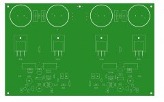
With these in mind i made a new lay out ( i think now i should be in version 125 or so) that features all of the above described goodies plus a couple new mostly in the power supply + some degeneration and its made to fit in a simple 2U chassis with drills onatop for ventilation and a simple but thick U shaped aluminum for heat sink ( given that bias will stay in a low to reasonable level )
Notice that transistors are mounted onatop but backwards so heat sink is directly screwed on them, the all board is to be secured on the chassis bottom ...
Will produce this pcb also , put it to work and evaluate the couple of new goodies and always post my findings here
Kind regards
Sakis
Box , case, chassis, looking good easy to produce but most of all in a reasonable cost was always the question in diy
Huge mistake everybody does including me is to design circuit and pcb and then look for the enclosure ...
Best way and more cost effective is to choose an enclosure and then built the pcb around it
With these in mind i made a new lay out ( i think now i should be in version 125 or so
) that features all of the above described goodies plus a couple new mostly in the power supply + some degeneration and its made to fit in a simple 2U chassis with drills onatop for ventilation and a simple but thick U shaped aluminum for heat sink ( given that bias will stay in a low to reasonable level ) Notice that transistors are mounted onatop but backwards so heat sink is directly screwed on them, the all board is to be secured on the chassis bottom ...
Will produce this pcb also , put it to work and evaluate the couple of new goodies and always post my findings here
Kind regards
Sakis
Attachments
- Home
- Amplifiers
- Solid State
- P3A Comparison table ( long .... )