Overshoot and ringing in feedback control systems is a bit of a special case. But notice that it's the Damping factor that determines it, with Damping = 0.7 (critcally damped) giving no ringing.
When not adjusting a feedback control system, i.e. when there is just a resonant LC circuit that is ringing when certain excitations are present, damping is still what is needed to quell the ringing. And damping implies using resistance, not capacitance.
Standard series-RC snubber networks are a good example of how that is largely misunderstood. Their main component, that damps the ringing, is the resistor. The capacitor is optional and is only needed if the power dissipation in the resistor would be too high and the capacitor is then used in order to allow only the unwanted higher frequencies to "see" the resistor. (Interestingly, exactly the same theory applies to damping reflections on transmission lines and digital busses.)
See my very short write-up about that, with a simple way to find the optimally-damping resistance value for any real-world circuit (as well as the appropriate range of capacitance values, if needed):
http://www.diyaudio.com/forums/powe...lm-caps-electrolytic-caps-30.html#post2828689
Hi There
get some live here.
I have also ringing and overshoot, but I see that as wel in the grounding as pulses 400mv pp if I go 20 volts output in 8 ohms wirewound resistor, what did I wrong, I have a supplys earths as a star to the center of the biggest supply, I use 2x 55 volts, 2x 120 volts (tube driver) and one 300 volts (tube voltage preamp).
photo 2 is a square wave trough 100k pot to srpp 6h8c it I set it full open the output of the signal generator distorts like on picture there is feedback trough earth I think, normally a tube is high input impedance and miller, the signal generator has a output amp of 5 watts so it is capable to drive.
how to earth this properly, I did see that if I play with a earth wire things change, so there is a earth problem, this amp is in testfase with a poor mans pcb as start so things can give problems.
there is here next door a powerfull wifi antenna who bundels rf power to 15 km away possible this thing gives problems because I see so now and then pulsing signal on output, even on the supplys.
But the sound, it is open and sweet I do like it.
thanks.
kees52,
If it's not just due to the inductance of the wirewound load, then read on.
Is there someplace in your circuit where an active device could be attempting to suddenly draw a fast-changing current from the supply rail? The inductances of the supply and ground rails would cause voltage spikes, on both, if fast edges of current were made to travel through the inductances, according to V = L di/dt (the basic ideal inductor equation). Even if the inductance L is very small, the time rate of change of the current (di/dt) might be very large, resulting in significant-amplitude voltage spikes that would correspond with the edges of pulses.
If so, a larger decoupling capacitor is needed, between that device supply rail point (right at the device) and wherever the ground is for where that current goes (possibly the closest load-ground point, but wherever works best). The decoupling capacitor can be thought of as a small point-of-load power supply and is needed to supply the current for sudden or transient demands, such as the leading edge of a pulse, so that a fast-changing or transient current doesn't have to attempt to travel through the inductance of the supply and ground rail conductors. (Also, make sure that the capacitor is not connected so that it shares any length of ground return conductor with any small-signal ground returns, as I think you already know.)
Take the worst-case (largest) change of current that might ever be demanded (call it di), and the shortest time in which the current change might have to occur (call that dt), and the largest voltage disturbance you want to allow on the power supply rail (call it dv). Then calculate an estimate of the minimum required ideal decoupling capacitance value with:
C ≥ di ∙ dt / dv
You might want or need to make the actual capacitor have a significantly-larger value than that.
You can also determine an estimate for how much length can be tolerated, in the conductors between the capacitor and the points to be decoupled, including the capacitor lead-spacing, by estimating the inductance that can be tolerated there and then estimating or assuming the self-inductance-per-inch of the conductors (typically 15 to 30 nH per inch):
L ≤ di ∙ dv / dt
If a capacitor has intrinsic inductance, besides what can be attributed to its lead-spacing, subtract that from L before estimating the allowable conductor length.
If the maximum tolerable inductance would be exceeded, you can use mutliple smaller capacitors in parallel, so that the parallel inductances will result in a lower overall inductance (much as paralleling resistors results in a total resistance that is lower than any of them). But note that for that to fully work, there can be no mutual inductance, which means that the parallel caps also cannot share conductors, to connect to the device's supply-decoupling points. All of their leads/traces/wires would need to stay separate, all the way to the points across which you are decoupling, if you want the lowest PSU impedance as seen by the device.
You could also think of all of the above in terms of the power supply impedance, AS seen by the active device, AT the device. For example, if a device might draw a current that could quickly change from 0 to 7 amps and you wanted the supply rail disturbance to stay below 0.1 volt, then an estimate of the required maximum target impedance that it sees across its supply terminals would be
Ztarget = dv / di = 0.1V / 7A ≤ 14.3 milliOhms (mΩ)
Then you have to make sure that the impedance of the network consisting of the decoupling capacitance, and its connecting conductors' self-inductances, and the capacitor ESR, as seen by the device being decoupled, is less than 14.4 mΩ over the entire frequency range of interest.
Note that for edges of pulses etc, the equivalent maximum frequency content can be calculated with
f ≤ 1 / (π ∙ trise)
Cheers,
Tom
Last edited:
Hi Tom.
Thanks, for your help, but in time I have make it good, problem was the supply, bad resistors in mosfet driver supply board, I have now regulated with mosfets, now it is oke, amps can behave strange sometimes...
now I have a very good sounding amp who has only P followers, except the fets, sound is very good, I have now H frames driven with this amp.
I have still a very little overshoot but I don,t think it is a problem, I can switch on and of the feedback.
sorry for the hollow sound, and bad film, it is made with a mobile phone, I have to make some day a better one with a real camera.
First H frame test with visaton wsp26s - YouTube
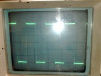
scope picture is 20 Khz square.
regards
Thanks, for your help, but in time I have make it good, problem was the supply, bad resistors in mosfet driver supply board, I have now regulated with mosfets, now it is oke, amps can behave strange sometimes...
now I have a very good sounding amp who has only P followers, except the fets, sound is very good, I have now H frames driven with this amp.
I have still a very little overshoot but I don,t think it is a problem, I can switch on and of the feedback.
sorry for the hollow sound, and bad film, it is made with a mobile phone, I have to make some day a better one with a real camera.
First H frame test with visaton wsp26s - YouTube
scope picture is 20 Khz square.
regards
Attachments
Overshoot
Overshoot is usually caused when an amplifier has problems driving a capacitive load. The problem can usually be eliminated by isolating the capacitive load from the source by either using either a series resistor or inductor just before the load. For power amplifiers it is common practice to use a 0.7uH inductor in parallel with a 10 Ohm resistor.
I need some help understanding the difference between overshoot and ringing. I read about the two as if they were related so I'll just mention that I understand that overshoot is the tendency of the amplified wave form produced from a square wave to overshoot and then oscillate a bit at the beginning of the square wave. I understand that by experimenting with some silver mica caps bypassing the negative feedback resistor one can eliminate the overshoot.
So assuming that's a relevant starting point, can someone please explain the concept of "ringing" to me?
Thanks
Overshoot is usually caused when an amplifier has problems driving a capacitive load. The problem can usually be eliminated by isolating the capacitive load from the source by either using either a series resistor or inductor just before the load. For power amplifiers it is common practice to use a 0.7uH inductor in parallel with a 10 Ohm resistor.
Overshoot can be caused by anything which boosts HF. Loop stability problems (short of actual oscillation) are one possible cause. Excessive capacitive loading is one possible cause of loop stability problems.
Ringing can be caused by an HF resonance, or a sharp filter which cuts HF.
Ringing can be caused by an HF resonance, or a sharp filter which cuts HF.
- Status
- This old topic is closed. If you want to reopen this topic, contact a moderator using the "Report Post" button.