DIY output transformers
Hi, harking back to GAK's original post, the 4th edition of the Radiotron Designers Handbook has the most comprehensive data available for transformer construction. Pps 216,217, provide a worked calculation which in eight simple steps covers 99% of the mystery. The same book contains comprehensive wire tables, the principal tool in any transformer construction. www.turneraudio.com.au provides ten pages of transformer calculation - following the RDHB closely....
http://home.mira.net/~kiewavly/8615tx.html reveals the winding data used in construction of Harold Leak's Stereo 60 amplifiers.
Personally, I have recently followed a winding-article appearing in Wireless World - January 1956. Authors were GEC-based and Gilson Transformers. They focus upon ultra-linear tranformers, and my efforts resulted in the two primary windings being within 0.4ohm of each other (DC) I also included cathode-feedback windings and on test the transformers do not reveal any resonances to to 200khtz.
I have used split-bobbins for SE tranformers with great success as the winding capacitances are reduced by a factor of four. Yes!!
the information how is included in the RDHB!!
My favourite insulation materials are: The hard, semi-translucent paper used by draughtmen - the rigidity greatly assists in layer-winding. Film cut from sheets sold as OverheadProjector film. This is also rigid and no doubt displays superior heat characteristics. Nomex-sheeting which I buy from local motor-rewinding firms. They are also my wire-source as they freely sell spool-ends of wire at scrap value.
You can achieve fine results - be patient - I think Turner notes your first efforts will be a disaster - but let it be a learning disaster!! I confess I have worked through a particular design and wound seven prototypes before being satisfied that I cannot take the design further. Measured results are way-ahead of most commercial transformers......
Weaaudio in Hongkong carry a simple hand-wound winding-machine. He lists on Ebay and I bought mine this year - at Buy-it-now listing.
Regards, Graeme
Your opinion, please
Hi guys,
I'm planning to build a tranny for a single 845 at 1000V x 90mA.
Approx Rp = 1700 Ohms.
Using a Z ratio of 750 (6000/8), my current thoughts are:
-Laminations: EI126-50 (42mm x 50mm core) M6X, with a 0.4mm gap.
-8 paralelled secondaries, 90 turns, 0.56mm dia, each fits in one layer.
-7 serialized primary sections, 354 turns, 0.28mm dia, each fits in two layers.
-0.5mm insulation at each primary to secondary boundary.
For 25W at 25 Hz, total induction should be 1.25 Tesla.
I expect a primary inductance of 30H and a leakage inductance less than 5mH.
Does someone find some gross error or have a better approach or any comment ?
Thanks for checking,
Yves.
Hello all!
I read all those articles about winding transformers some years ago, I'm on winding transformers since 1975 or earlier. This doentn't make me Nobel Prize rewarded, but as many of you know, during life there is ollways a time for doubt and questions.
And since I've never made a splitted windings transformer for a PP this question arised in my mind. Probably, this is not worth the time spent to investigate, but none fo the books or articles on tranformers lingers so much on small magnetics fenomena occurring on a OPT. Nevertheless I agree with Yvesm that this could be a really small and negligible effect.
About the core used by Yvesm, I used the same size core for a 50W PP, so if this is for a 25W class A SE it could be a little oversized but not excessively much. A little bigger core is allways better than a litle smaller one.
Best regards.
I'm not an expert on this or winding my own OPTs.
But I read somewhere that SE OPTs are so much different from PP OPTs.And core size is calculated much more different.
I remember that the core size ratio btw SE and PP OPTs is 1:10.
This means that a core that is suitable for 10W SE OPT is also suitable for a 100W PP.
So what kind of core is suitable for 25W SE???
I remind you that I'm not an expert on this.Just posting what I remember that I had read.
I'll try to find it and post it here as it is.
Due to some problems with my PC I lost a lot of articles
Maybe this problem is because SE OPTs are gapped.I also remember a member who says "that's why the best sounding SE amps are all below 10W"
Hello,
Hi Resident.
There are many kind of PP OPTs as there are many kind of amplifiers. You are fully right, if you compare a guitar o vox amp with a Hi-End class A SE amp, ten times the weight is close the reality. But the topic was Hi-End PP AB1 amplifiers, so 1.5 to 2 times is a close aproach for SE of the same power.
This is not "the bigger the better", neither is "the smaller the better". Still there is a kind of parameter histeresys in chosing iron it must be as close as power requirements are, if you are looking to optimize things.
Sincerely.
Hi Resident,
I think an SE vs PP transformer ratio of 10 is a lot o iron, there are a mix of ways to determine the iron weight for a transformer, all are not scientific formulas are all of them gives different results. But ten times is still a lot of difference. I'm winding a PP OPT for a 25 to 50 Watts amp, and the iron is about 10 pounds. Thinking of a same power amp with a 100 pounds OPT makes me shiever, don't you?
Usually a 1" X 1" cross section E I line power transformer of a no waist type lamination can handle abou 1KW @ 50Hz. With a flux aprox. of 1.5 Weber/m² but it results to 500W @ 25Hz or 250W @ 12.5Hz. And the power drops if you like to have only 1 Wb/m² to about 150W or only 75W if you like your amp to go down to 7Hz. This is for a PP OPT. If you aim for an SE OPT you must allow for no more than a 0.8 Wb/m² and a gap or even less if you don't add a gap.
It depends largely in what are your requirements. But ten times bigger....
Nevertheless I can be wrong.
Cheers
Larry.
I think an SE vs PP transformer ratio of 10 is a lot o iron, there are a mix of ways to determine the iron weight for a transformer, all are not scientific formulas are all of them gives different results. But ten times is still a lot of difference. I'm winding a PP OPT for a 25 to 50 Watts amp, and the iron is about 10 pounds. Thinking of a same power amp with a 100 pounds OPT makes me shiever, don't you?
 Idon't mean in pounds but in watts.
I mean that you need the same core for a 10W SE with a 100W PP amp.Or the same core for a 5W SE with a 50W PP amp.
Determining the core size (cross section) isn't easy enough.
And depends a lot of times in number of turns and interleaving.
For example I have seen an OPT for a pair of 6L6GC and an OPT for two pairs of 6L6GC and they were the same size.
SE OPTs are different from PP OPTs due to the big gap andwinding technique.
A 5W SE OPT can't be the same with a 10W SE OPT.
Nice to read you Resident,
I'm sorry for misunderstang, I agree that it is not so easy to determine "exaclty" the core size for each aplication, but roughly the flux density for a line power transformer made of silicon oriented steel cut in the usual "no waist" shape, must non be stronger than 1.5 Wb/m². Same iron for a PP OPT can be crossed by a flux not stronger than 0.8 Wb/m² and an SE OPT, same material, the flux crossing it must not be stronger than 0.5 Wb/m².
Now this shows no relation betwen power and frequency. The bigger the core the lower the frequency. Doubling core cross section doubles the power or lowers 1/2 lower frequency for the same power.
Since commercial transformers are made that way you can use an existing one for different tubes or chose to made it yorself. Sometimes this is the trade to go throug. It, possibly, could be the case of your tranny.
A good old formula to know a cross section in Cm² (square centimeter) is to multiply 20 by the square root of the secundary power divided by the frequency in Hz at wich you like the tranny to start to be frantic.
For more, and accurate, formulas you can poke around to find the Radiotron book and look at chapter 5. In fact, I recomend you to read it carefully before starting a new project.
Sincerely.
Larry.
Confused by units
Hey Larry,
You are speaking in Wb/m² !
I confess that the most bothering thing about magnetism is the mess in unities, some being even related to "imperial" units like inches and feet.
I routinely use Teslas for flux density, is it a relation with Wb/m² ?
Yves
Hey Larry,
You are speaking in Wb/m² !
I confess that the most bothering thing about magnetism is the mess in unities, some being even related to "imperial" units like inches and feet.
I routinely use Teslas for flux density, is it a relation with Wb/m² ?
Yves
I allready have Radiotron book.Very nice book.
I have learn a lot from it.Chapter 5 is for transformers,right?
I don't believe that this formula is very accurate determining core cross section.Because what will happen if the amp is only 2-3W?Say a SE one with 2A3.
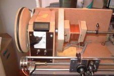
By the way, you have posted a pic with a very nice bobbin.Where do you find it?Do you wind OPTs with this kind of bobbin?
I have learn a lot from it.Chapter 5 is for transformers,right?
I don't believe that this formula is very accurate determining core cross section.Because what will happen if the amp is only 2-3W?Say a SE one with 2A3.
By the way, you have posted a pic with a very nice bobbin.Where do you find it?Do you wind OPTs with this kind of bobbin?
Thank you so much Resident, you are the first one to say that my bobbin is "Nice". I made it with a unique system and a very special material. It took me a lot of time to design it and a lot of effort, becouse I think this is a very important part of a transformer......but.....everybody told me this is "Ugly". And I become to start to believe in that.
It is made from a shet of Tufnol 6F/45 a very good material with high quality characteristics such as isolation, strengt etc... But it is utterly ugly!
Never mind. If you like I can post a picture of the plans. But don't blame me if your neighbors say it is ugly.
Lets talk about the 2-3W SE OPT, I think this could be impossible to wind by yourself. I have an allmost the same OPT for an EL84 SE ampli from the roarings past years and it looks winded up with airs, well, I had two once ago. One was noto functioning properly so I unwinded it. Now I have the row core. No way to wind tens of tounsands of turns of 0.01mm dia wire, wether interlived or not. This is becouse I made no amp under 25-50 W. This formula isn't too accurate for those small trannies if it is not accurate at all. But a reference point to start....
And for Yvesm I think a flux density of 1 Tesla is the same amount of 1Weber/m², this is becouse a Weber is the measure unit of the flux. And a flux of one Weber per square meter is a Tesla. I hope so.
Have you passed a driver licence exam in the USA? I did, they asked me how I was tall, I answered 1m 80Cm. The sheriff: "What is this, man?", so how is your weigt? About 85Kg....
How many cubic inches is your engine capacity? And what wrench is needed to unscrew the licence plate? 1/2" is for the wrench for the engine capacity I still don't know.
Hi Resident and Larry
Well Larry, it's your answer, but it was not the question !
You talks about an EL84 while Resident spoken about about 2A3.
The main difference resides in widely different Rp, some tens of KiloOhms for the penthode and less than 1KOhm for this triode.
For that reason, we don't need huge primary inductance, just 12 Hys are needed for a -3dB point below 10Hz.
This can be acheived with relatively low count number on a reasonnably sized iron. This being favourable to reduce leakage inductance.
A possible "compromise" (because any OPT IS a compromise) could be:
Core type EI66B (Tonge=22mm x stack=35mm core).
A gap of 0.15mm, should reduce the permeability down to 800.
It is possible to put 1750 turns (in 3 sections) of 0.2mm dia for the primary interleaved between 4 paralleled secondaries, each 78 turns 0.32mm.
A 0.5mm thick insulation at each primary to secondary boundary fits in the copper window.
This turn ratio reflects a 3K5 at primary when loaded by 7 Ohms.
compromise !
The predicted AC induction for 3 Watts at 25 Hz is 0.77 Tesla, while the DC one for 0.05A plate current is 0.57, reaching a total of 1.34.
Just acceptable with M6X steel grade, but at 30Hz, it falls down to 1.2 ... compromise !
The main compromise is in the copper losses that reach 15%, but this is less than 1dB, still acceptable.
In true, this what I've used as a "minimalist" approach and sounded good to my ears even if 100Hz square showed some 30% "tilt".... compromise !
At the other end of spectrum, rise time was less than 5µs. Not so bad !
With all that compromises, this much better than many commercial designs
Me too !
NO, but how many miles per gallon ?
Yves.
I don't believe that this formula is very accurate determining core cross section.Because what will happen if the amp is only 2-3W?Say a SE one with 2A3.
Lets talk about the 2-3W SE OPT, I think this could be impossible to wind by yourself. I have an allmost the same OPT for an EL84 SE ampli from the roarings past years and it looks winded up with airs, well, I had two once ago. One was noto functioning properly so I unwinded it. Now I have the row core. No way to wind tens of tounsands of turns of 0.01mm dia wire, wether interlived or not.
Well Larry, it's your answer, but it was not the question !
You talks about an EL84 while Resident spoken about about 2A3.
The main difference resides in widely different Rp, some tens of KiloOhms for the penthode and less than 1KOhm for this triode.
For that reason, we don't need huge primary inductance, just 12 Hys are needed for a -3dB point below 10Hz.
This can be acheived with relatively low count number on a reasonnably sized iron. This being favourable to reduce leakage inductance.
A possible "compromise" (because any OPT IS a compromise) could be:
Core type EI66B (Tonge=22mm x stack=35mm core).
A gap of 0.15mm, should reduce the permeability down to 800.
It is possible to put 1750 turns (in 3 sections) of 0.2mm dia for the primary interleaved between 4 paralleled secondaries, each 78 turns 0.32mm.
A 0.5mm thick insulation at each primary to secondary boundary fits in the copper window.
This turn ratio reflects a 3K5 at primary when loaded by 7 Ohms.
compromise !
The predicted AC induction for 3 Watts at 25 Hz is 0.77 Tesla, while the DC one for 0.05A plate current is 0.57, reaching a total of 1.34.
Just acceptable with M6X steel grade, but at 30Hz, it falls down to 1.2 ... compromise !
The main compromise is in the copper losses that reach 15%, but this is less than 1dB, still acceptable.
In true, this what I've used as a "minimalist" approach and sounded good to my ears even if 100Hz square showed some 30% "tilt".... compromise !
At the other end of spectrum, rise time was less than 5µs. Not so bad !
With all that compromises, this much better than many commercial designs
And for Yvesm I think a flux density of 1 Tesla is the same amount of 1Weber/m², this is becouse a Weber is the measure unit of the flux. And a flux of one Weber per square meter is a Tesla. I hope so.
Me too !
Have you passed a driver licence exam in the USA?
NO, but how many miles per gallon ?
Yves.
Hello folks,
Hi Yvesm,
I made some class A SE using 300B, some using EL84, some using 811 and also 813, a huge one using QB3/300, some using 807, and finally using KT88. But I have never made amps with smaller tubes an neither using a 2A3. So you are the expert.
I like PP ones, with some extra power. I think that a good PP tube amp is better than any solid state, this is a good target. I like to make experiments like the one with QB3/300 but an experiment is just what it is.
Good luck with your OPT.
Five or Six in a Chevy Firechicken ....... Firebird, it was 1978!
Hi Yvesm,
I made some class A SE using 300B, some using EL84, some using 811 and also 813, a huge one using QB3/300, some using 807, and finally using KT88. But I have never made amps with smaller tubes an neither using a 2A3. So you are the expert.
I like PP ones, with some extra power. I think that a good PP tube amp is better than any solid state, this is a good target. I like to make experiments like the one with QB3/300 but an experiment is just what it is.
Good luck with your OPT.
but how many miles per gallon ?
Five or Six in a Chevy Firechicken ....... Firebird, it was 1978!
hahahahahaha.....lolHave you passed a driver licence exam in the USA? I did, they asked me how I was tall, I answered 1m 80Cm. The sheriff: "What is this, man?", so how is your weigt? About 85Kg....
How many cubic inches is your engine capacity? And what wrench is needed to unscrew the licence plate? 1/2" is for the wrench for the engine capacity I still don't know.
Larry you are a very funny person.
I agree with this.It took me a lot of time to design it and a lot of effort, becouse I think this is a very important part of a transformer
Yes I like your bobbin.It's look like a vintage bobbin and I like vintage things.No problem if you would like to post or e-mail me the plans.But where can I find this material?And how can I do the cuts?
Also,
from where do you buy cores?
I think you must split the primary in more sections.Core type EI66B (Tonge=22mm x stack=35mm core).
A gap of 0.15mm, should reduce the permeability down to 800.
It is possible to put 1750 turns (in 3 sections) of 0.2mm dia for the primary interleaved between 4 paralleled secondaries, each 78 turns 0.32mm.
A 0.5mm thick insulation at each primary to secondary boundary fits in the copper window.
This turn ratio reflects a 3K5 at primary when loaded by 7 Ohms.
compromise !
As I know a good SE OPT needs more than 4 or 5 sections.
I have seen a SE OPT with 12 in series primary and 12 paralleled secondary sections.
Very difficult to wind it but ... it wasn't for commercial use!
You can split it in 6 or 7 and you will have much more better results.
Do you have a winding machine or you wind by hand?
0,2mm dia would be difficult to handle.
Hi Resident !
May be, may be not !!
The goal is to have tight coupling between primary and secondary.
To do that, any part of primary must be as close as possible to any part of the secondary, and splitting winding help to achieve that.
The smaller the tranny, the easier to achieve, the less interleaving is necessary to reach a given leakage inductance.
A larger tranny would certainly ask for more sections, but this also increases the parasitic capacitance, so thicker insulation must be used, wasting space in copper window, needing to use smaller dia wire .... or larger iron, wich need more interleaving ... and so on !
Compromise !!!
Was not that the "Art Of Engineering" ?
A diy one !
I think you must split the primary in more sections.
As I know a good SE OPT needs more than 4 or 5 sections.
I have seen a SE OPT with 12 in series primary and 12 paralleled secondary sections.
Very difficult to wind it but ... it wasn't for commercial use!
You can split it in 6 or 7 and you will have much more better results.
May be, may be not !!
The goal is to have tight coupling between primary and secondary.
To do that, any part of primary must be as close as possible to any part of the secondary, and splitting winding help to achieve that.
The smaller the tranny, the easier to achieve, the less interleaving is necessary to reach a given leakage inductance.
A larger tranny would certainly ask for more sections, but this also increases the parasitic capacitance, so thicker insulation must be used, wasting space in copper window, needing to use smaller dia wire .... or larger iron, wich need more interleaving ... and so on !
Compromise !!!
Was not that the "Art Of Engineering" ?
Do you have a winding machine or you wind by hand?
0,2mm dia would be difficult to handle.
A diy one !
Attachments
Hello everybody,
Hi resident,
You are right stating that it is impossible to made two sections equal each other, but.... williamsons OPTs were made that way, and how could be significant the difference between the two sections compared to the tubes tollerance? Splitting the windings in two section there could be a lesser stray capacitance at least 1/4 times the same windings on one section, as is stated on chapter 5 of the Radiotron. This is why I'm experimenting it. Till now I winded all my transformers with 5 to 9 interwinding layers but in one section only and they are working very fine. Now, I have to find somenting else to make things worse
Next, the material is from RS-COMPONENTS Tufnol, it comes in sheets of 1feet by 3 feet by 2 or 4 millimithers thick.
All I used to work the material is a jigsaw and a milling machine with a bit of 4mm. After all pieces are finished, I assembled them out and glued togheter with a cianoacrilic (loctite) glue. It holds very tight with tufnol material, the right way it is needed for the pourpose.
I allways use normal silicon grain oriented steel same used in line transformers, since I like to build bigger transformer than needed since I found the bass extension very pleasent. So I find the use of extra permeability cores expensive and not so convenient.
The core for the bobbin is 1" by 1" square EI type.
Nevertheless I think, sometime in the future, I'll try a double C core from Metglass, but is still not very easy to find that material in Saudi Italy.
http://www.metglas.com/tech/index.htm
Here are the pictures of the making of the bobbin from the sheet, I think they are explainfull, if they aren't, ask an I'll post you the blueprints.
Sincerely Larry.
Hi resident,
You are right stating that it is impossible to made two sections equal each other, but.... williamsons OPTs were made that way, and how could be significant the difference between the two sections compared to the tubes tollerance? Splitting the windings in two section there could be a lesser stray capacitance at least 1/4 times the same windings on one section, as is stated on chapter 5 of the Radiotron. This is why I'm experimenting it. Till now I winded all my transformers with 5 to 9 interwinding layers but in one section only and they are working very fine. Now, I have to find somenting else to make things worse
Next, the material is from RS-COMPONENTS Tufnol, it comes in sheets of 1feet by 3 feet by 2 or 4 millimithers thick.
All I used to work the material is a jigsaw and a milling machine with a bit of 4mm. After all pieces are finished, I assembled them out and glued togheter with a cianoacrilic (loctite) glue. It holds very tight with tufnol material, the right way it is needed for the pourpose.
I allways use normal silicon grain oriented steel same used in line transformers, since I like to build bigger transformer than needed since I found the bass extension very pleasent. So I find the use of extra permeability cores expensive and not so convenient.
The core for the bobbin is 1" by 1" square EI type.
Nevertheless I think, sometime in the future, I'll try a double C core from Metglass, but is still not very easy to find that material in Saudi Italy
.http://www.metglas.com/tech/index.htm
Here are the pictures of the making of the bobbin from the sheet, I think they are explainfull, if they aren't, ask an I'll post you the blueprints.
Sincerely Larry.
An externally hosted image should be here but it was not working when we last tested it.
An externally hosted image should be here but it was not working when we last tested it.
An externally hosted image should be here but it was not working when we last tested it.
An externally hosted image should be here but it was not working when we last tested it.
- Status
- This old topic is closed. If you want to reopen this topic, contact a moderator using the "Report Post" button.
- Home
- Amplifiers
- Tubes / Valves
- output transformers