Hi,
I have a headphone amp that I have been working on for a while. It is up and running, and in its current version is a 6N6p on each side (with both sides in parallel) transformer coupled to a pair of headphones.
The headphones have a 32R impedance. The transformers are 5K:8. I have a 33R resistor in parallel to the headphones, so 10K o nthe plates.
Anyhow, the question is that the bass response is a bit weak. Sound otherwise is great, and on recordings with plenty of bass the bass is nice, but if the recording is bass shy at all, then the amp is all midrange.
So, is there a better way to set this up? No resistor, a bigger resistor, or would I be better off with transformers with a true 32 ohm tap? Is it the tube choice -- though 6922s sounded about the same?
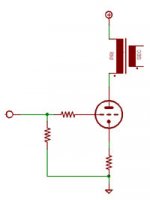
Also, for now the tube's cathodes are resistor biased and are not bypassed in case that matters. Basic schematic is attached
I have a headphone amp that I have been working on for a while. It is up and running, and in its current version is a 6N6p on each side (with both sides in parallel) transformer coupled to a pair of headphones.
The headphones have a 32R impedance. The transformers are 5K:8. I have a 33R resistor in parallel to the headphones, so 10K o nthe plates.
Anyhow, the question is that the bass response is a bit weak. Sound otherwise is great, and on recordings with plenty of bass the bass is nice, but if the recording is bass shy at all, then the amp is all midrange.
So, is there a better way to set this up? No resistor, a bigger resistor, or would I be better off with transformers with a true 32 ohm tap? Is it the tube choice -- though 6922s sounded about the same?
Also, for now the tube's cathodes are resistor biased and are not bypassed in case that matters. Basic schematic is attached
Attachments
dsavitsk said:Hi,
...Anyhow, the question is that the bass response is a bit weak. Sound otherwise is great...
... though[t] 6922s sounded about the same?
Don't know if it is related to your issue but I have a KT88 SE amp (monoblocks actually) that use a 6N1P as the input/driver. When I changed that for a 6922 the amps definitely became bass-shy. Listening tests with other people confirmed it.
If you have a 6N1P laying around try plugging it in and see if it changes things. (Be careful though, heater current on the 6922 is 300mA and the 6N1P is 600mA. Make sure your heater secondary can supply the needed current.)
Re: Re: Output transformers and frequency response
SE Trafo, and I am running tham at about 20mA while the transformers can take up to 65mA or so.
I figured that since the plate resistance of these tubes is low enough, especially in parallel, that not bypassing would not be a huge deal since the plate load is 10K. I did try LED biasing, and while the bass is a bit better, the midrange is not as good -- I am not sure I like this LED bias thing so much, sounds a little flat and hard to me. I'll try some capacitor bypasses tonight, but I was hoping to keep them out of the signal path.
No problem on the heaters, but no real change either.
Geek said:Hi,
Are you using a SE (gapped core) transformer?
If not, the core is saturating.
If so, the primary inductance may not be sufficient for the plate Z, or Z ratio.
SE Trafo, and I am running tham at about 20mA while the transformers can take up to 65mA or so.
AndreasS said:The plate resistance of the tube is increased by degeneration; try bypassing the cathode resistor.
I figured that since the plate resistance of these tubes is low enough, especially in parallel, that not bypassing would not be a huge deal since the plate load is 10K. I did try LED biasing, and while the bass is a bit better, the midrange is not as good -- I am not sure I like this LED bias thing so much, sounds a little flat and hard to me. I'll try some capacitor bypasses tonight, but I was hoping to keep them out of the signal path.
Sherman said:If you have a 6N1P laying around try plugging it in and see if it changes things. (Be careful though, heater current on the 6922 is 300mA and the 6N1P is 600mA. Make sure your heater secondary can supply the needed current.)
No problem on the heaters, but no real change either.
According to theory, when you 'ratio' a transformer it shifts the frequency response. For example, if you were to take a transformer designed for 5k:8 and instead used it as 20k:32 then the frequency response would be shifted up. Both the low end and high end cutoff would go up; you would lose low frequency response in exchange for high frequency response.
I understand that with the parallel resistor you are not really doing that, so you shouldn't be losing bass this way... according to the theory. I do believe in theory, but I also believe in the tremendous amount of unknowns we're dealing with.
Anyway, the lack of bass could be due to a lot of things, but my thought is that it would be pretty easy for you to experiment with different parallel resistors just to see what happens.")
We could also talk about taking the transformers apart and experimenting with the gap. It's not as difficult or scary as you might think. If the OT's were designed to handle more DC idle current than you're putting through them then a smaller gap might bring out more bass. Finding the balance that you like is largely a matter of experimentation.
-- Dave
I understand that with the parallel resistor you are not really doing that, so you shouldn't be losing bass this way... according to the theory. I do believe in theory, but I also believe in the tremendous amount of unknowns we're dealing with.
Anyway, the lack of bass could be due to a lot of things, but my thought is that it would be pretty easy for you to experiment with different parallel resistors just to see what happens.
We could also talk about taking the transformers apart and experimenting with the gap. It's not as difficult or scary as you might think. If the OT's were designed to handle more DC idle current than you're putting through them then a smaller gap might bring out more bass. Finding the balance that you like is largely a matter of experimentation.
-- Dave
The lack of cathode bypasses does seem to be a big part of it. I added 470uF BG caps bypassed by 0.1uF Vit Q's and the bass is back. However, I don't think the midrange is nearly as good. It is just a little sloppy-er sounding. I think I'll try ultrapath bypasses next to see how that does.
As for regapping the transformers, they are potted in epoxy, so I am guessing that it is not going to work. However, I am going to order some electra-prints to upgrade a bit so perhaps I'll talk to Jack about optimum gapping.
-d
As for regapping the transformers, they are potted in epoxy, so I am guessing that it is not going to work. However, I am going to order some electra-prints to upgrade a bit so perhaps I'll talk to Jack about optimum gapping.
-d
33R resistor in parallel to the headphones = 50% output power loss. I think, that Ra=10k is no proper for two parallel connected triodes, rather 3.5k or 2.5k .
http://www.shinjo.info/frank/sheets/113/6/6N6P.pdf
http://www.shinjo.info/frank/sheets/113/6/6N6P.pdf
Zibi said:33R resistor in parallel to the headphones = 50% output power loss. I think, that Ra=10k is no proper for two parallel connected triodes, rather 3.5k or 2.5k .
...
The output power isn't important for a headphone amp; but a higher load decreases the distorsions (btw. the transformer is 5 kohm to 8 ohm).
Andreas
As for transformer theory..it is all very predictable by math to match what you get in "reality"....
The key thing is to note the -3dB roll off point in the Low frequency response...refered to as LF POLE....
The -3dB point is defined as when the Inductive reactance = (plate load//plate resistance), i.e.. when your Inductive reactance equals the plate load in parallel with the plate resistance.
For example...lets say you have 20H of inductance at full power output...and the plate load is suppose to be 5K ....
Looking at the data curves in 20mA region, it is safe to say the plate resistance of tube is 2K ohms.....
So 5K//2K = 1428 ohms.... So the -3dB frequency would be 11.4Hz.....
Now lets change the plate load to 10K......
10K//2K = 1666 ohms..So -3dB frequency would be 13.3Hz.....
Not a drastic change since it is a TRIODE where the plate resistance dominates...with a pentode, then the results would vary a lot more, since the PLATE LOAD would dominate in that case...
This is based off assuming 20H inductance..we will need to find out what yours are.....
You could put two of these Triodes in Parallel...the 10K load won't hurt at all since were dealing with triodes....only the high frequency response "could" suffer ...
So recalculating for two paralle triodes....
10K//1K = 909 ohms...This is a -3dB at 7.2Hz.... Which WILL give you a respectable low frequency response for SE amp....
The 10K plate load will not hurt anything and will be technically fine..
The main thing to watch for is the cathode bypass caps will need to be HUGE to get the proper low frequency response.... and will create phase shift and audio quality issues..
Your best bet is to eliminate the cathode resistor all together and go straight to ground....then provide a negative grid voltage of -2 to -4 range..... That should fix the problem your having, just make sure you use proper size bypass caps for the grid bias return since this will affect frequency response..... but if you need more bass response...then additionally you could try to use two of these Triodes in parallel totalling 40mA of DC Q-current..... And maintain the 10K load with the 33 ohm resistor across the secondary...make sure your 33 resistor is large enough to not get too hot...
Chris
cerrem said:
And maintain the 10K load with the 33 ohm resistor across the secondary...make sure your 33 resistor is large enough to not get too hot...
Chris
What do you think about using one triode per channel with Ra=20k ? It will be more efficient, than heating output resistor.
You could use the OPT as 20K plate load if the 32 ohm headphones are connected to 8 ohm winding....
The real problem here is the high frequency response getting pretty bad.... The leakage inductance would need to be known to see where the roll-off begins..BUT you have winding capacitance that will make a peak due to change in Q from the higher load at 20K... Sometimes if the Capacitance is just right... what happens is that the it will bring the high frequency back up without peaking and it will look like flat response... This can happen by accident if your lucky....
Also the unbypassed cathode resistor rasies the plate resistor, while this is bad for bass but it helps the high frequency response...
If the transformer specs are posted.... I can calculate the frequency response for various scenarios...
The main thing is to remove the cathode resistor and ground the cathode...use fixed bias at the grid.... this will probably do the most to bring the bass back nicely...
Chris
cerrem said:So 5K//2K = 1428 ohms.... So the -3dB frequency would be 11.4Hz.....
Now lets change the plate load to 10K......
10K//2K = 1666 ohms..So -3dB frequency would be 13.3Hz.....
I missed a step here. How do you go from 1428 ohms to 11.4Hz?
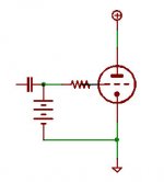
cerrem said:The main thing is to remove the cathode resistor and ground the cathode...use fixed bias at the grid.... this will probably do the most to bring the bass back nicely...
Is this the way to battery bias the grid? I assume that cap is necessary on the input?
Attachments
OK...
Like I mentioned....
You take the plate resistance, 2K, and parallel it with the plate load of 10K for example....
2K//10K = 1666 ohms.....
Now you need to find the frequency at which the inductive reactance = 1666 ohms....
The equation for inductive reactance is XL= (2*pi*fr*L) ....
So set (2*pi*fr*L) = 1666 ohms.....
Re-arrange equation for finding frequency ....
fr= 1666/(2*pi*L) ......
2*pi = 6.28 ...
So, fr= 1666/(6.28*L) ...
So if L = 20H for example.... the fr= 1666/125.6 = 13.26Hz for your -3dB POLE...... remember that means you have 45 degrees of phase shift at that frequency as well...
Phase linearity is very critical in audio.... since having a 45 degree shift at 13.26Hz means you have 33.55 degree shift at 20Hz..... For example....if this example X-former had 60H then your -3dB point would be at 4.4Hz and at 20Hz you would have 12degrees of phase shift... Low frequency phase shift is not as critical and no need to break your neck to achieve it...What is important is the phase shift at 20Khz, that is why you want the High Frequency Pole as high as possible...in some of my designs I have it as high as 86kHz for the -3dB pole...
Now this is assuming that you have no cathode feedback issues...
Such that you go directly to ground with your cathode...
Using a battery is good idea for the grid...... I would use two 1.5V batteries in series to bias this circuit to -3 volts at grid.....
Chris
dsavitsk said:
Is this the way to battery bias the grid? I assume that cap is necessary on the input?
Here's an example with a transformer instead of cap. If your source has either, you wouldn't need another.
Sheldon
Hi dsavitsk, your diagram is missing a grid resistor in series with the battery. As shown the source is effectively shunted to ground at AC. Also, since the battery has a very low AC impedance the corner frequency against any reasonable input cap value is probably in the AM band.
- Status
- This old topic is closed. If you want to reopen this topic, contact a moderator using the "Report Post" button.
- Home
- Amplifiers
- Tubes / Valves
- Output transformers and frequency response