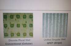
While I’m in the process of regurgitating, here is little more about mosfets. Vertical type generally have much higher Gm and thus higher Ft. This can be a problem in that the frequency operating limit must be set externally so they do not oscillate and cause RF ringing. They are designed for switching and low Rds on is the aim. Generally there are a few types of vertical power mosfets, trench, hex (plural well), or planer stripe (single well). (photo 1)
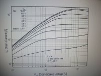
Cgs stays dominate with trench fets. Trench fets are not suitable for analog power usage because they tend to ‘hot spot’ very much like BJT’s do but for different reasons. This limit’s the reactive power they can handle. Stay away from trench fets for this purpose, they really are switching transistors. For the other types, Cds increases exponentially at Vds saturation. This means it takes more di/dt to pull the device out of saturation, ie a stronger driver stage. Hex fets and planer stripe fets are suitable for analog applications and tend to be very rugged. I have been impressed by the abuse planer stripe fets can take. However, they do show a tendency to have a greater dependence of Gm upon Vds much more than the plural well devices (photo 2). Vds breakdown determines how wide the channels are, and this affects Pd. When choosing a fet, you want to balance Vds breakdown with Gm. Generally, higher Vds max = lower Gm. Higher Gm = higher capacitances. As per the second photo in post 16, choosing N-ch and P-ch devices with similar Gm is important. This in itself limits the choices available. Sifting through the other criteria along with what is available price wise will limit even further the optimum choices.
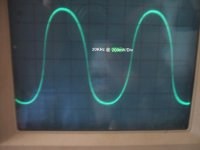
To show more detail of the varying Gm of mosfets, measurements were taken of an amp I made last year using planer stripe fets. The output stage uses a high frequency local error correction scheme with the bias setting extra low, about 15mA. In post 24 of this Thread here, you can clearly see the drop in Gm at the zero current crossing in the triangle wave when driving a resistor; dv/dt is not linear for the gate drive signal and shows the greater change in Vgs vs Id at the zero current crossing required to yield a linear output from those transistors. The the last photo below is the difference between the gate drive signal and the output. You can clearly see the significant increase in slope of this 'error signal' at the zero current crossing. The steeper the slope, the higher the frequency of the error signal required. It can be seen here that there are frequencies involved that are much higher than 20KHz. Also the slope is not symmetrical when comparing positive side to negative side reflecting the differing Gm between the N-ch and P-ch devices. Without the local error correction, the inverse of that garbage is what will be combined in the input stage of the amplifier through the global loop. No wonder vertical mosfets have such a bad reputation for use in class AB. The local loops significantly nullify this effect so the limited bandwidth global loop is not disrupted in such a significant way. While it is quite possible to use vertical mosfets to create a low distortion high fidelity power amplifier, it is more involved than simply substituting vertical fets for BJTs.

Cgs stays dominate with trench fets. Trench fets are not suitable for analog power usage because they tend to ‘hot spot’ very much like BJT’s do but for different reasons. This limit’s the reactive power they can handle. Stay away from trench fets for this purpose, they really are switching transistors. For the other types, Cds increases exponentially at Vds saturation. This means it takes more di/dt to pull the device out of saturation, ie a stronger driver stage. Hex fets and planer stripe fets are suitable for analog applications and tend to be very rugged. I have been impressed by the abuse planer stripe fets can take. However, they do show a tendency to have a greater dependence of Gm upon Vds much more than the plural well devices (photo 2). Vds breakdown determines how wide the channels are, and this affects Pd. When choosing a fet, you want to balance Vds breakdown with Gm. Generally, higher Vds max = lower Gm. Higher Gm = higher capacitances. As per the second photo in post 16, choosing N-ch and P-ch devices with similar Gm is important. This in itself limits the choices available. Sifting through the other criteria along with what is available price wise will limit even further the optimum choices.
To show more detail of the varying Gm of mosfets, measurements were taken of an amp I made last year using planer stripe fets. The output stage uses a high frequency local error correction scheme with the bias setting extra low, about 15mA. In post 24 of this Thread here, you can clearly see the drop in Gm at the zero current crossing in the triangle wave when driving a resistor; dv/dt is not linear for the gate drive signal and shows the greater change in Vgs vs Id at the zero current crossing required to yield a linear output from those transistors. The the last photo below is the difference between the gate drive signal and the output. You can clearly see the significant increase in slope of this 'error signal' at the zero current crossing. The steeper the slope, the higher the frequency of the error signal required. It can be seen here that there are frequencies involved that are much higher than 20KHz. Also the slope is not symmetrical when comparing positive side to negative side reflecting the differing Gm between the N-ch and P-ch devices. Without the local error correction, the inverse of that garbage is what will be combined in the input stage of the amplifier through the global loop. No wonder vertical mosfets have such a bad reputation for use in class AB. The local loops significantly nullify this effect so the limited bandwidth global loop is not disrupted in such a significant way. While it is quite possible to use vertical mosfets to create a low distortion high fidelity power amplifier, it is more involved than simply substituting vertical fets for BJTs.
Attachments
Last edited:
Re-read all the papers on ALFET, SANGEN, VISHAY and EXICON. All of them suggest V FETS were designed for switching do to their lower Ron but very high capacitance and L-FETS designed for linear amplifiers. We do use parts for non-originally intended use all the time, but this is what the manufactures are saying. From these papers, trench and hex are just two types of V-FETs.
Maybe it is just my way of looking at things, but I would think twice before I go use a part where the manufacture says it is the wrong application.
All MOSFETS are susceptible to parasitic oscillation.
Maybe it is just my way of looking at things, but I would think twice before I go use a part where the manufacture says it is the wrong application.
All MOSFETS are susceptible to parasitic oscillation.
I tend to look at things for what they are. Can this part be used for this purpose? Maybe, maybe not. Due to the physics and internal components of that particular device it may be unsuitable or perhaps can work very well. The circuit design surrounding it may need to be manipulated in some way from the typical but it doesn't mean it won't work. Just because a manufacturer designs a part for a particular purpose does not mean it is limited to only that purpose. I say this only because I have made some pretty good output stages using vertical fets.
I have designed numerous irfp240/9240 amplifiers from 300 watts to 1500 watts.
They all sounded very good.
A transistor doesn't have to be linear to give a linear output.
The feedback loop ensures you get out what you put in or at least 99.9%
Look at class d that outputs square waves (on/off) and filters to give audio signals out.
They all sounded very good.
A transistor doesn't have to be linear to give a linear output.
The feedback loop ensures you get out what you put in or at least 99.9%
Look at class d that outputs square waves (on/off) and filters to give audio signals out.
Many of our best VAS transistors are described asRe-read all the papers on ALFET, SANGEN, VISHAY and EXICON. All of them suggest V FETS were designed for switching do to their lower Ron but very high capacitance and L-FETS designed for linear amplifiers. We do use parts for non-originally intended use all the time, but this is what the manufactures are saying. From these papers, trench and hex are just two types of V-FETs.
Maybe it is just my way of looking at things, but I would think twice before I go use a part where the manufacture says it is the wrong application.
high definition television (CRT)
and yet are superb for some Audio duty.
Re-read all the papers on ALFET, SANGEN, VISHAY and EXICON. All of them suggest V FETS were designed for switching do to their lower Ron but very high capacitance and L-FETS designed for linear amplifiers. We do use parts for non-originally intended use all the time, but this is what the manufactures are saying. From these papers, trench and hex are just two types of V-FETs.
Maybe it is just my way of looking at things, but I would think twice before I go use a part where the manufacture says it is the wrong application.
All MOSFETS are susceptible to parasitic oscillation.
HEXFET vertical MOSFETs make excellent output stages when properly applied. Their relatively high gm is an advantage (it is still quite a bit smaller than that of BJTs.
See my MOSFET power amplifier paper on my web site at CordellAudio.com - Home. It was probably the first amplifier to get below 0.001% THD at 20kHz. Certainly the first MOSFET. It was the first application of HEC to MOSFET power amplifiers.
Proper application requires taming any tendency to parasitic oscillation, as they are very fast (equivalent ft in the hundreds of MHz). Layout is important and it is desirable to use Zobel networks in the gate circuits; see my paper.
They should also be driven by an emitter follower buffer so as to reduce the effect of capacitance when being driven near the rails. It is a common misnomer that Cgs is large and a problem. It is in fact hugely smaller than that of a BJT that is turned on. It is an insignificant problem when output stage source followers are used because it is bootstrapped.
Cheers,
Bob
Bob, Yea, I reread your paper earlier today and will re-read the full chapter again. I wonder if the folks who had so much trouble with the capacitance did not use a suitable driver stage? Even on laterals, I see the temptation to drive with a small VAS directly. The B&K's did that which makes me wonder if that was the source of their lack of dynamics, or "no balls" if you will?
Could it be the comparison between laterals and various verticals commenting on the Cgs? I did read one paper talking about the "trench" transistors showing in depth why they have serious hot spot issues if used as linear devices. I may have to build a HEXFET I guess.
I still suggest for most of us, we should pay attention to what the chip designer says until we know better. Then let folks like yourself and our friend Mr. Pass lead the way.")
How about laterals for the driver stage?
Could it be the comparison between laterals and various verticals commenting on the Cgs? I did read one paper talking about the "trench" transistors showing in depth why they have serious hot spot issues if used as linear devices. I may have to build a HEXFET I guess.
I still suggest for most of us, we should pay attention to what the chip designer says until we know better. Then let folks like yourself and our friend Mr. Pass lead the way.
How about laterals for the driver stage?
Thanks for all the info in this thread - it has helped convince me to go in the direction of well matched (p-n) vertical FETs. There are a lot of sources that make clear the need for a good driver stage and many good examples showing how to do it (and what to avoid). When going to all the effort to design a good amp, what would be the point of skimping in this area?
Bob, Yea, I reread your paper earlier today and will re-read the full chapter again. I wonder if the folks who had so much trouble with the capacitance did not use a suitable driver stage? Even on laterals, I see the temptation to drive with a small VAS directly. The B&K's did that which makes me wonder if that was the source of their lack of dynamics, or "no balls" if you will?
Could it be the comparison between laterals and various verticals commenting on the Cgs? I did read one paper talking about the "trench" transistors showing in depth why they have serious hot spot issues if used as linear devices. I may have to build a HEXFET I guess.
I still suggest for most of us, we should pay attention to what the chip designer says until we know better. Then let folks like yourself and our friend Mr. Pass lead the way.
How about laterals for the driver stage?
Yes, I also read somewhere that trenchfets are not suitable for audio output stages - it is effectively an SOA problem - just like the hot spots you mentioned.
Not sure about laterals for the drivers. Just haven't thought about it enough to have an idea of what they bring to the table compared to BJTs for drivers.
Cheers,
Bob
All MOSFETS are susceptible to parasitic oscillation.
Correct, this is also the case for BJTs.
one thing i try to avoid at all costs is rail sticking. if you can keep the amp well behaved at clipping, the occasional clipped peak won't be so noticeable when playing music near full power. rail sticking is also one of the factors in an amp being a "tweeter eater".
with bjt outputs, this means avoiding saturation.
with bjt outputs, this means avoiding saturation.
Last edited:
I modeled my "Reasonable" amp with L-fets as drivers leaving the BJT outputs. Because they have a higher drop, they prevent the output from reaching the rails, so no rail-stick. Very clean clipping AS PER SPICE. I do loose several volts of overhead. This was a tip M.I . led me to look at when I suggested some of the "SOP" I see in almost every amp did not look as well thought out as it could be, output stage base starvation for example. Compensation becomes 2Vce. So, better behaved or more overhead? The obvious solution is slightly higher rails. Distortion modeled in the same range. .001 vs .002 something.
So I started thinking today, how about using them for the VAS with a BJT output? Would it be possible to skip the driver stage without causing undue harm where a BJT VAS takes at least the driver stage, and preferably two?
So I started thinking today, how about using them for the VAS with a BJT output? Would it be possible to skip the driver stage without causing undue harm where a BJT VAS takes at least the driver stage, and preferably two?
Hi,
Personally, I had in my last build more detail and contrast when using fet's (2sk216/2sj79) as drivers compared to bjt's (tried 3 different complementary pairs), I had a FET OPS. For a BJT OPS, the Gm of these latfet's would be to low.
In my work in progress amp (see link), I'm starting with FET's in the VAS (9610/610) and Driver section (2013/313). Experimenting with the Vbe multiplier will be the hardest part (hopefully), the drivers will be placed on seperate smaller heatsinks.
There are not that much commercial amp's using fet's as drivers (parasound, classe, zeck, a few sony's) that I know of. I wonder why?
http://www.diyaudio.com/forums/soli...-scratch-low-nfb-fet-front-end-bjt-ops-2.html
OEM's and fets: Accountant looks at a $1 FET and a $.20 BJT. Simple.
I have been resting migration to FETS in my project as if I want a nice FET front end, I just go into the living room. I have three HCA's.
On thermal compensation, L-FET drivers with BJT or V-FETS outputs, I need something close to 2Vce compensation. SOP on the bias servo is typically about 10:1 current through the resistors vs. the bias transistor. So, if I changed the ratio to 1:1, would that not give 50% compensation without adding a second transistor to the string?
Wow, nice, three Parasound amp's. I presume you must be very happy with the sound than? Did you compared them with other "famous" amp's?
Regarding the bias spreader; I use a second transistor for 2 reason's,
- monitoring and compensation of the ambient temperature
- decrease the bias spreader's Zout = much less sensitive to dynamic VAS currents.
Regarding the bias spreader; I use a second transistor for 2 reason's,
- monitoring and compensation of the ambient temperature
- decrease the bias spreader's Zout = much less sensitive to dynamic VAS currents.
- monitoring and compensation of the ambient temperature - decrease the bias spreader's Zout = much less sensitive to dynamic VAS currents.[/QUOTE said:Hmm, that's interesting. I can understand the advantage of keeping Zout low but what is the benefit of tracking the ambient temperature - surely it is only the output transistor junction temperature that you need to track.
Well, I have the FET drivers mounted on two smaller heatsinks to have no extra temperature variation from the OPS. But the ambient temperature inside the amp enclosure can vary from 20C to something like 40C. This variation will also be "seen" by the drivers. This variation, I would like to compensatie with the extra transistor.
So, in conclusion, it seems that the best design uses vertical MOSFETs ...
Anyone not agree?!!
Hi,
I completely disagree. What you want is low intrinsic distortion
at low power, not meaningless numbers related to the last
3dB of the amplifiers dynamic range, hardly ever used.
In all respects, except for Class A, BJT output devices simply
out perform MOSFETs in all low level distortion respects.
rgds, sreten.
Well:
1. Performance criteria: As I see it, THD must be one of the most relevant criteria in terms of defining an amplifiers ability to do its job without (negatively) affecting the signal content. Of course it would be silly to strive after super low THD figures and totally disregard other important factors such as transient response, ability to deal with difficult loads etc. Intrinsic distortion is a new one om me - what is that?
2. From a THD perspective, I agree that BJTs should give better performance but am not sure how valid this is in practice due to the difficulties in bias tracking with respect to temperature. This is one of the reasons (apart from robustness, etc) for the vertical MOSFET conclusion - assuming the amplifier is correctly designed (driver stage, layout, etc.).
3. The whole reason for starting the thread was to get these different opinions. You are not the only one to promote the BJT output stage - what is your main reasoning?
- Status
- This old topic is closed. If you want to reopen this topic, contact a moderator using the "Report Post" button.
- Home
- Amplifiers
- Solid State
- Output stage transistor type