Yes , 16-60R would cover most earbuds.
The BJT circuit below would even power a more current hungry set of
headphones.
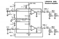
Here is a link to the excellent LM4881 IC board -
Sure Electronics AA-AB32261 Stereo 2 x 150mW Class AB LM4881 Headphone Amplifier Board
The 4881 has the buck convertor - you can run it from a single 5V USB.
If you want a project , there are many IC based kits on ebay for <10$.
Edit - here's another .... http://www.parts-express.com/sure-e...ass-ab-headphone-amplifiers-2x1w-kit--320-319
TDA2822 with RCA inputs. PE has many of these kits.
OS
The BJT circuit below would even power a more current hungry set of
headphones.
Here is a link to the excellent LM4881 IC board -
Sure Electronics AA-AB32261 Stereo 2 x 150mW Class AB LM4881 Headphone Amplifier Board
The 4881 has the buck convertor - you can run it from a single 5V USB.
If you want a project , there are many IC based kits on ebay for <10$.
Edit - here's another .... http://www.parts-express.com/sure-e...ass-ab-headphone-amplifiers-2x1w-kit--320-319
TDA2822 with RCA inputs. PE has many of these kits.
OS
Attachments
Last edited:
This circuit that I'll be building isn't actually going to be used in the long term. It's merely just for learning. Using an OP-amp anywhere in the circuit is kind of defeating the purpose of what I'm trying to achieve. My design goal is to have an output impedance as low as is physically possible, while outputting a voltage amplitude and current that would be required of any typical earbuds (not necessarily apple).
So from what you guys are saying, it seems like it would help to also have a feedback loop going from the output stage output back to the VAS input in addition to biasing the output stage with a ridiculously high current?
So from what you guys are saying, it seems like it would help to also have a feedback loop going from the output stage output back to the VAS input in addition to biasing the output stage with a ridiculously high current?
Hi Guys
The idea that output impedance is related inversely to idle current is true in a limited context. However, with feedback the relationship is made less important and even a low idle current output stage can have a very low z-out.
There are good reasons to have a very low z-out inasmuch as the amplifier behaves more like a true voltage source which is ideal. But... too low a z-out can lead to high-frequency instability. This is why headphone amps designed as such often have a 1-2R resistor in series with the output. Personally I think it's better to have a choke and zobel just like a larger amp, but there is a tradition of design lethargy when it comes to "low power". Designers equate it to "low quality" but you don't have to.
You began the thread with a specific requirement to drive earbuds. Now you are suggesting that you are just playing with circuits to learn. In either case, a given project has to be given parameters to make the design logical. If the end goal is to have the headphone amp but you want to try different things to get there, that is fine. Others need to know what the goal is to be able to provide the advice you need.
Have fun
Hi,
Your assumptions are all wrong regarding achieving low output impedance.
You can't optimise a problem when you don't understand the issues involved.
One assumption that is clearly wrong is that using op-amps defeats the purpose.
It doesn't at all. Feedback doesn't care about the devices used and is the main
arbiter of the effective output impedance of any output stage if it used.
Enter op-amps. They allow simple circuits with lots of feedback,
and far lower output impedance than the open loop output of
their basic output stage topologies.
NwAvGuy: O2 Summary
On this site you can find far more about headphone amplifiers
than you will ever sensibly need to know, it's a tour de force.
rgds, sreten.
FWIW 4 ohms for Apple earbuds is utter nonsense.
Last edited:
I meant it would defeat the purpose of why I'm doing this which
is to learn. I'm effectively implementing what's inside an op-amp
thus obtaining a much deeper understanding of what's going on.
Hi,
No your not. If you don't know how to use op-amps you will
gain nothing implementing what you think is better than an
op-amp, because your simply wasting your time and effort.
Simple fact is anyone with a deep understanding will
understand why op-amps are the way they are, and
why its pretty pointless to build your own "op-amps".
Your not effectively implementing "inside an op-amp",
your implementing what you think should be inside
an op-amp, without any real world understanding.
That does not lead to deeper understanding, in that
how the op-amp is used determines the parameters,
not the features of it you seem to think matter.
rgds, sreten.
Having said the above you can of course build
an all discrete "op-amp" and try to optimise its
features, but open loop low output impedance
is a very poor feature to optimise in reality.
Current delivery is an entirely different matter,
as open loop and closed loop is nearly the same.
Last edited:
All you're debating is my approach to learning. While there may be
benefits to initially taking a higher level approach to learning this
stuff, I don't think they're necessarily that profound over starting
with a discrete level approach.
Hi,
Fact is pontificating about design at a discrete level without
understanding how it is properly used is pointless. It is just
pontification, not remotely any deeper understanding.
It in fact makes no difference. If you don't understand the
higher level general concepts, you'll always talk nonsense.
Your way out of your depth in discussing output impedance.
rgds, sreten.
Last edited:
Every audio beginner wants to play with a handful of BJTs just as many students of electronics have done since transistors first became popular. There is folklore being parroted on the myriad internet audio beginner forums and educational sites, that there is audio magic and lots of parts to poke and prod about and create nice sound effects with, when you use discrete designs. So the spark of inspiration is out there.... the purpose of why I'm doing this which is to learn. I'm effectively implementing what's inside an op-amp thus obtaining a much deeper understanding of what's going on.
Not so with ICs. These are a sealed deal and no fun. Unfortunately for emulation, much of the internal circuitry does not translate to discrete parts anyway because of fabrication techniques. The schematics you see are also representative but not detailed, nor exact or reproducible. Still, the big issue with creating discrete circuits is that unless you have some practical and formally organised training in component level electronics, this will always be either copying what others publish or just fiddling and listening to accidental results. You may like the sound effects of some poorly operating circuits, but never stumble upon on a correctly operating one without being shown by others. This is really a form of creative captivity - trapped in a lack of understanding.
Many people have tried and continue to try to make discrete power amplifiers based on sections at least, of the popular ICs from the past. You can tell by the verbose topologies and overkill attempts to get very low THD and higher power where this is often a waste of effort and resources.
May I suggest you start instead with very basic but appropriate discrete designs and only elaborate them where there is a clear and defined need for improvement by measurement. Yes, measure because without measurement, you learn nothing that can be communicated accurately or compared intelligently.

Hi Gorge,
Well, why don't you go with a hybrid approach to get your feet wet?
Use an op-amp, and all of the built-in wonderfulness that they offer, and just put a push-pull follower, using discrete devices, as a current stage to follow it. There'll be all kinds of design levers that you can pull and you can focus on what an output stage does. At the end of the day, though, your device selection will depend on Icc, Pd, and the impedance of the load. Those will be the low hanging fruit parameters.
With a setup like that, you won't spend a whole lot of time chasing down catastrophic, avalanche failures. ....if,should,when they occur.
anyway, patronizing aside, this is the circuit i'm going to set out to make and measure the output impedance.
Basic Audio Amplifier
Basic Audio Amplifier
Hi,
FWIW that is a very poor circuit, and so as not
to be patronising I'm not going to tell you why.
You research and work out why, try D. Self.
rgds, sreten.
I keep trying to tell you open loop output impedance
is pretty much irrelevant, but you simply won't listen.
FWIW that is a very poor circuit, and so as not
to be patronising I'm not going to tell you why.
You research and work out why, try D. Self.
rgds, sreten.
I keep trying to tell you open loop output impedance
is pretty much irrelevant, but you simply won't listen.
Last edited:
Gorge - I understand the appeal of personally re-creating the history of solid-state audio amplification as a learning tool. There's nothing wrong with that approach, as far as I'm concerned.
That said, the specific circuit you show is incomplete, and, in my opinion, has a number of other issues. For example:
1) Why do Q6/Q7 not have emitter resistors?
2) Where will Vbias come from?
3) Where will Vsig come from?
4) What sets the DC voltage at the output, i.e., how do you keep lots of DC volts from appearing across the load, Rl?
5) What happens when the temperature of the output devices change, and they require lower Vbias to avoid self-destruction?
There are other issues too, for example, the circuit as shown will have considerable amounts of (nasty-sounding) crossover distortion.
What you're looking at is a circuit that is intended for simulation only, where you can just plop down AC or DC voltage sources anywhere in the circuit. This is convenient for a learning exercise using simulation software.
In engineering reality, those voltage sources have to be implemented somehow as voltage drops based on current flows in the circuit.
There are plenty of practical, complete, discrete transistor power amplifier circuits out there if you look for them.
One question: what, in your opinion, is the benefit you would gain from having the lowest possible output impedance? (I'm asking for the objective, technical reason why this is a good thing, based on your current understanding of the subject.)
The reason I'm asking is that engineering parameters are rarely set in "lowest possible", or "maximum possible" terms. For an analogy, a car engine needs to make some power; more power is desirable; but "as much horsepower as possible" would not make sense - what fraction of people would want a 15,000 horsepower car, and who could drive it without instantly frying the tyres, and maybe killing themselves?
So if you were in charge of deciding how much horsepower a new car should have, you would probably start by calculating how much horsepower is practical, and worth paying for. You might use a target performance ("zero to 100 kmph in 5 seconds or less"). Or you might find out how much power commercially available tires in the size you need can handle.
Along the same lines, let's say your proposed circuit had a very high output impedance of 10 ohms. What is the bad thing that would happen as a result?
Suppose you lowered that to 1 ohm. What would be better, and by how much? Would this be a worth-while improvement, and why?
Supposed you lowered that to 0.1 ohm. Same questions: what is the benefit gained compared to 1.0 ohms? Is it worthwhile?
Obviously, you can extend this chain of questions indefinitely. Would 0.01 ohms be better than 0.1 ohms? Why? Would 0.001 ohms be better than that? Why?
Here's something related to consider: the DC resistance of the coils in the headphones is already part of the circuit. In your case, that's 4 ohms, nominal. So, if your headphone amp circuit has a supposedly appallingly high 4 ohm output resistance, that only doubles the total resistance in the circuit, from 4 ohms to 8 ohms. A 100% increase in resistance.
If you got the headphone amp down to 1 ohm output impedance, you now have 5 ohms total, instead of the 4 ohms of the headphones only. Okay, that's 25% more resistance.
Suppose you managed 0.1 ohm. Well, that's only 2.5% more resistance than the headphones already have. More importantly, the headphone cable probably has more than 0.1 ohm resistance on its own, so now the wires leading to the headphones swamp out any supposed benefit of lower output resistance from your amp. You basically can't get below 4.1 ohms, total, no matter what you do with the amplifier.
If you took this line of reasoning, you might conclude that you are going to shoot for 0.1 ohms output resistance. Now you have something concrete, rather than "the lowest possible resistance".
The next step would be to find out if it's practical to achieve 0.1 ohms without a very complex circuit - what would it take to get there?
I cannot speak for anyone else, but let me assure you that I have no intention at all of being patronizing. I'm trying to help you get a start on where you want to go. And I'm trying to help you stay away from audiophool pitfalls such as "lowest possible" or "maximum possible", that come with no practical benefit, but considerable practical costs.
-Gnobuddy
Thanks for the helpful post.
Yes, I also just noticed that the circuit doesn't have bias resistors. This makes me wonder how their spice file even works.
In regards to output impedance, I said that I wanted the lowest output impedance based on the assumption that there were no trade-offs and that it wouldn't affect anything else. With the issues you've brought up, I'll aim for a compromise.
My system will have a bandpass filter with a pass-band between 10Hz-2Khz, so the high frequency issue at low output impedance isn't something I need to worry about since my highest frequency of interest isn't actually very high.
Last edited:
anyway, patronizing aside, this is the circuit i'm going to set out to make and measure the output impedance.
Basic Audio Amplifier
That's a wikipedia circuit and it's not at all practical. It's not even complete. And it won't have low output impedance (or linearity) unless it's included in the feedback loop of a voltage amplifier.
Why not just build a cmoy? It's simple, almost foolproof, and it works.
My concern with the smaller transistors is that having a large amount of current flowing through them will cause temperature to increase which will cause beta to increase. And this will be a self-reinforcing cycle.
Sure, I could use negative feedback, but that will reduce their gain and therefore decrease the input impedance to the output stage.
The problem with bigger transistors is their large collector capacitance which will increase cross-over distortion due to not turning off before the opposite polarity transistor turns on.
Perhaps I should just go with the smaller transistor+negative feedback and produce more gain than I require in the VAS, and lose some voltage at the input to the output stage (due to its now lower input impedance).
Last edited:
My concern with the smaller transistors is that having this amount of current flowing through them will cause temperature to increase which will cause beta to increase. And this will be a self-reinforcing cycle.
That's thermal runaway. You can design around that.
Your circuit has unity voltage gain. Feedback won't even work without a voltage gain stage.Sure, I could use negative feedback, but that will reduce their gain and therefore decrease the input impedance to the output stage.
What do you propose for Vbias?
Build your circuit and make your measurements. Don't expect a practical circuit.
My concern with the smaller transistors is that having a large amount of current flowing through them will cause temperature to increase which will cause beta to increase. And this will be a self-reinforcing cycle.
Sure, I could use negative feedback, but that will reduce their gain and therefore decrease the input impedance to the output stage.
The problem with bigger transistors is their large collector capacitance which will increase cross-over distortion due to not turning off before the opposite polarity transistor turns on.
Perhaps I should just go with the smaller transistor+negative feedback and produce more gain than I require in the VAS, and lose some voltage at the input to the output stage (due to its now lower input impedance).
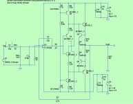
Then you use a class A output stage with a local current limiting FB loop.
That would be like (below).
Q7/8's thermal/beta would rise , Q5/6 would counteract this.
Q3/4 are current sources for the diamond (Q1/2).
The drawback is for a stereo pair - .3 -.5A total current ,depending on how
many diodes (D3/4 - or even another one ).
The 2 big semi's (Q7/8) could be ksa1381/ksc3505 - low Cob.
You would have to mount them on the chassis or a heatsink , they
pass 60-100ma each.
This is the price you must pay to mitigate the issues you mentioned.
OS
Attachments
Sorry for not being clear. I meant it decreases the effect their beta has on the current gain, not the voltage gain.That's thermal runaway. You can design around that.
Your circuit has unity voltage gain. Feedback won't even work without a voltage gain stage.
What do you propose for Vbias?
Build your circuit and make your measurements. Don't expect a practical circuit.
Under the heading "high input z" on this page it talks about the effect of the Beta of the output transistors on the input impedance to the output stage.
Basic Audio Amplifier
That is unless I'm wrong, and negative feedback doesn't reduce the effect beta has on current amplification, but only voltage amplification.
So, why do you need a large amount of current?My concern with the smaller transistors is that having a large amount of current flowing through them will cause temperature to increase which will cause beta to increase. And this will be a self-reinforcing cycle.
Let's suppose you want to target 0.1 ohms output resistance. (By the way, I would probably only target 0.4 ohms, which is ten times lower than the 4 ohm headphone resistance; there is in fact no practical benefit to going beyond this, only empty bragging rights. If lower output resistance comes along as a byproduct of other design decisions, sure, it's welcome, but irrelevant.)
The output resistance of a common emitter stage, if we make some simplifying assumptions, is 26/Ie, where Ie is the emitter current in milliamps. So: 1 mA gives us 26 ohms, 26 mA gives us 1 ohm, 260 mA gives us 0.1 ohm. (The last two numbers may not be correct, because that simple equation doesn't take into account things like the resistance between the transistor terminal and the actual semiconductor chip inside, etc).
The circuit you suggested won't work on a low supply voltage; at least 2.4 volts is lost in the various transistor junctions. Let's say you decide to run the thing at a nice round 10 volts. At 260 mA, you have 2.6 watts of heating. I've used ten-watt soldering irons that got hot enough to melt metal; 2.6 watts is quite a lot of heat to deal with! Small transistors are out, heatsinks are in, and you have a headphone amp that's hot, huge, and horribly inefficient.
Now, we know there are very good headphone amps out there that are small, light, and efficient. So we're doing something wrong - there must be a better way.
Let's try the feedback approach. Run the transistors at a reasonable 10 mA, for a dynamic output resistance around 2.6 ohms. Apply feedback that reduces the voltage gain by a factor of 26 (that's less than 30 dB), and you have your target 0.1 ohm output resistance. That's more like it!
Note: 0.1 ohm output resistance does not guarantee your amp doesn't still have much worse problems, such as, say, an appalling 1% harmonic distortion.
This is erroneous information. There are essentially four possible types of negative feedback; you can take the feedback from the output current, or the output voltage, and you can apply it either in series with, or in parallel with, the input signal. That gets you the four possibilities.Sure, I could use negative feedback, but that will reduce their gain and therefore decrease the input impedance to the output stage.
Two of these four types of negative feedback increase the input impedance, not decrease it!
Audio electronics is at a very strange point in history. In the early 20th century, it was researched by smart and educated people, who worked for actual scientific organizations such as Bell Labs. By the late 20th century, these people solved virtually all the actual technical problems, allowing the design of amplifiers that are essentially perfect (remaining imperfections are too small to hear, only to measure.)
But in the meantime, a strange set of superstitions grew around audio. Many people with limited education and no technical ability started spouting complete nonsense about audio, which was taken up and reinforced by other equally ignorant people. Since the engineering problems were essentially solved, the qualified people, for the most part, moved on to new, still unsolved problems elsewhere in electronics (not audio). So audio was increasingly left to a few qualified people, and a growing crowd of lunatic-fringe enthusiasts making increasingly weird and nonsensical claims.
What this means to you: if you're trying to learn electronics from the Internet, expect that 99% of the material you find by random search will be complete nonsense.

Obviously there is still good information to be found, but you have to be very picky about the source, to have a chance of finding it, buried as it is in the middle of endless nonsense.
Again, time for quantitative questions. How slow are these bigger transistors, actually? In 2016, when gigahertz electronics is entirely routine, do we really still have to worry that our transistors are supposedly so slow that they cannot handle 20 kHz? (That's at least a hundred thousand times slower.)The problem with bigger transistors is their large collector capacitance which will increase cross-over distortion due to not turning off before the opposite polarity transistor turns on.
Let's see, thousands of very smart, well educated electronics engineers have already chosen that route - it's in virtually all opamps and class AB low power chip amps, so it's probably a good choice!Perhaps I should just go with the smaller transistor+negative feedback and produce more gain than I require in the VAS,
A complete non-issue, not even correct, unless you apply parallel feedback to the input, as mentioned above.and lose some voltage at the input to the output stage (due to its now lower input impedance).
-Gnobuddy
- Status
- This old topic is closed. If you want to reopen this topic, contact a moderator using the "Report Post" button.
- Home
- Amplifiers
- Solid State
- Output stage power