If you ever have seen a SS amplifier go dc and destroy a irreplaceable vintage woofer-I think more people would be less concerned about the sound of the relay vs protecting their precious speakers.
If you have a fuse-it might help-better then nothing. If your speakers have a crossover cap in the woofer section even better.
The best solution IMHO is a self powered protection box, you can move from amp to amp, or remove if you like.
Most of the new speaker protection kits use standard relays-you could always get a couple and seal them up for the future.
Most of these can also be installed in the amp by someone competent.
Vintage direct coupled amps-if you refuse to use a protection circuit-should at least be checked out for bad/cold solder joints etc, and any overheated components, and limit their 'on time', and make sure you check there bias/idle current-as a few mv of dc can dramatically increase distortion (especially in the high frequency range)- ideally you should be below 15mv.
I like the idea of direct coupled-and currently have one myself- but IMHO your playing with fire-especially if you have a set of expensive/and/or irreplaceable speakers.
"The best solution IMHO is a self powered protection box, you can move from amp to amp, or remove if you like."
Just build a Triac crowbar with an SBS driving it, use a large value fuse inline (for the Triac to crowbar).
See various circuits from Quad, Peavey, QSC, etc. It can be a two-terminal device, three if you want a fuse.
Just build a Triac crowbar with an SBS driving it, use a large value fuse inline (for the Triac to crowbar).
See various circuits from Quad, Peavey, QSC, etc. It can be a two-terminal device, three if you want a fuse.
One thing I haven't seen in this thread is mention of using redundancy.
If for instance a circuit has a five percent chance of failing over a particular interval then you can put its reliability as = 1-.05 = .95, if however you use double redundancy then this becomes = 1- 9.05)^2 = .9975, a lot better.
If for instance you put two relays in series, and have a separate lot of sensing circuits for each you then have a voting circuit, both must agree or the speaker is not connected, this is the sort of thing done in aerospace design.
As to contact oxidisation most speakers produce about at least two orders of magnitude more distortion than this does at its worst.
rcw
I'm worried too when connecting my precious spk. to chip amps(LM1875) I'm currently making. They are powered by 2 independent smps (o/p 21V for + & 21V for -) joined in series. Even if 1 of them fails, a massive DC of 21V 4A lightning strike. Though the sound is good for chips costing just about 1$. Right now working on UPC1237 ckt. design based on this ELECTRONICA / components | projects | applications. And yes having two independent protection module did crossed my DIY mind
Overall many years of experience do indicate that the ESP idea of using a relay with changeover contacts connected to earth is the simplest and most reliable one for most diy purposes.
You can of course get contactors with arc quenching magnets and sealed relays filled with SF6 and so on, but unless you can get surplus ones cheap you quickly end up with a protector that costs more than the protected .
Posted on the ESP site there are a series of tests very informative tests done by done by Halfgaar. these show that the changeover contact scheme does kill the arc in around a ten millisecond average, and that a capacitor resistor snubber also works, but its value is very dependent upon how fast the relay switches, and this can vary quite a bit.
The Amplimo dual contact relay also effectively kills the arc, but failed during the tests and does not have changeover contacts.
rcw
If you ever have seen a SS amplifier go dc and destroy a irreplaceable vintage woofer-I think more people would be less concerned about the sound of the relay vs protecting their precious speakers.....- ideally you should be below 15mv.
I like the idea of direct coupled-and currently have one myself- but IMHO your playing with fire-especially if you have a set of expensive/and/or irreplaceable speakers.
I agree, & in my opinion speaker protection is an absolute necessity. I think that the issue of relay (polyswitch, fet etc.) noise is an oxymoron, with the emphasis on the 'moron' bit.
As a listener, I dont care about the horrible noise protection makes, because I dont listen at levels that strain the power supply and drive components. If my relay or fet or thermistor act on a short circuit in the output transistor or speaker, then the salvage is usable. Many people wrongly assume that DC protection is necessary for normal listening conditions, and of course it is not.
I have a mate that calls himself an audiophile - a term that I dislike. He says his NAD has a soft clipping circuit and it makes a horrible noise frequently when he is listening to his panel speakers at his shack up at the Great Lake in Tasmania. I reckon he is deaf and his amp is doing a good job after 30 years of faithful service.
Well bloke, I hope you have a better run next time. I know how it feels to loose an old friend.
Sincerely, Phil Elliott
I have been applying some thought. One needs to build a matrix chart to list the various faults that need mitigation and the various parts of the speaker and amp system that need to be protected. Reading the available papers and comments made by several folks who actually build amps for a living, I can appreciate that there is no single correct solution.
What do you need to protect?
* Normal operation (turn on and off)
* Speaker faults. ( open, short, strange load causing instability)
* Amp faults. (DC, instability, or excessive signal)
* Source faults. ( the old dropping the tone arm problem)
* Operator faults. (too many to list)
* Power faults ( transients, brownouts)
What methods do we have and their limitations?
* Fuses are slow and sound bad
* Relays almost as slow and sound bad
* Crowbars fast but destroy the amp
* Sensing circuits can fail themselves or false trigger
* Inherent protection (cap in tweeter for DC)
This is a darn hard problem folks. The only thing I might suggest is that vintage wonder speaker is probably not as good as a modern one, so maybe the loss is more emotional than real. Drivers have come a LONG way. That bank of Hitachi MOSFETS are something else.
Staged relays, fuses and DC monitoring seem to be the options we have to live with, so the question is how to do that best we can. I do wonder, could those massive class A jobs the good Mr. Pass is fond of be so robust that they could withstand a crowbar/fuse system?
PS: The list of faults is far from complete. I lost a tweeter one time because a joker had a 1000W amp on his CB radio and I picked it up in the speaker cable. Somehow it wound up rectified and through the feedback I heard "Brea...pip" and that was all it took. I have to admit I solved both sides of the problem. Kimber did not pick up the noise and somehow that guys illegal amp failed shortly thereafter.
No relay "oxidation"?
My experience with power amplifier relays is that they do indeed gain a layer of filth by oxidation or rather sulphation, contamination or arcing residue that can noticeably affect the sound we hear at the speakers. In fact, I've spoiled my chances of a decent repair charge more than once by just cleaning the relay contacts and admitting to the customer that this was the main reason his 20-30 year old amplifier sounded so poor.
I've also built amplifiers for clients that don't use output relays or protection of any kind other than rail fuses. This flies in the face of the concerns expressed here, though I have learned over the years that there are only a couple of dominant problems in domestic situations that call for speaker protection. The first is careless misuse of the level setting and this is followed by horribly cobbled-together speaker leads and that most unsuitable of connection systems, the stone age banana plug. These easily short in domestic situations where there is free access around the rear of the equipment and children play, cleaning gets done and leads easily slip out and short. This is made even worse by solid metal plugs which immediately short if accidentally wrenched out whilst the music plays. I think I'm careful but it has happened to me too, on the bench. 'Just a split second and then no output stage.
Learn where the CD clipping point is on your volume control, mark it and fix any output connection problems. Use genuinely secure (don't accept marketing hogwash about popular types) connectors. It's just a matter of reliably low resistance, security and insulation from nearby conductors - period! Do this right and most of the issues for accidental shorts disappear.
This isn't just a problem with old gear. Modern products such as the current Marantz 7000 series amps. feature closely grouped speaker thumbscrew connections, which are all but guaranteed to short as you fiddle with connections. These and similar fittings are bad news, even though covered by comprehensive protection circuits.
I guess what is an unproven design or of doubtful construction will always remain a significant risk to speakers and amps but why do we still connect our valuable speakers to dodgy prospects anyway? If we must run risks then let's develop fast, reliable electronic methods to mitigate against the known problems with elecromechanical systems and be done with it.
Brian I guess you refer to this: http://www.linearaudio.nl/HP14570-1.htm
I've been using this and a similar design with a PIC controller for audio power sequencing.
jan didden
I've been using this and a similar design with a PIC controller for audio power sequencing.
jan didden
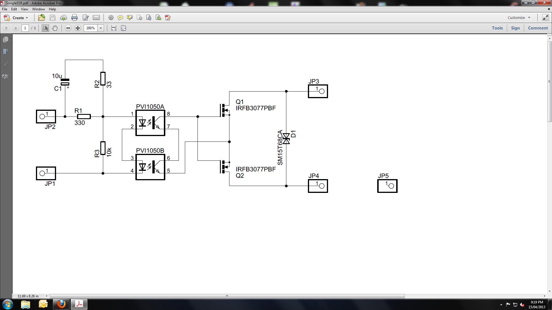
Here is the circuit and PCB layout for a solid state relay. This is just the relay part. There are a few notes on how to apply the relay.
Solid State Relay with PCB Layout
")
Solid State Relay with PCB Layout
Hi Bonsai,
A very professionally produced document there
I notice you use two couplers in parallel whereas I use two in series to get a higher drive voltage for the FET's. I wondered (and I realise its FET dependent) whether worst case voltage output from a single coupler at around 7 volts was "enough" to absolutely fully turn a FET on when its passing its max drain/source current. In other words to get the Rds as low as possible.
Good point Mooly. I never tried the optos in series, only in parallel where I am looking for fast switching speeds.
The design shown here is basically what I am using in my e-Amp with great results. You need to use mosfets with logic level thresholds for the best results. Over driving them in general will give you lower Rdson, but for the devices shown using TLP191s total end to end Rdson is still under 15 miliOhm.
The design shown here is basically what I am using in my e-Amp with great results. You need to use mosfets with logic level thresholds for the best results. Over driving them in general will give you lower Rdson, but for the devices shown using TLP191s total end to end Rdson is still under 15 miliOhm.
Hi Bonsai,
I agree the FET relays are great and I'd never go back to mechanical now, and using logic level FET's makes sense, the 7 volt drive should fully turn them on.
Excellent
(Have you tried... just for sonics and fun, using dis-similar FET's. One a low Rds and one a high Rds device to add purely second harmonic distortion ? It works well in simulation but I don't know how well in practice)
I agree the FET relays are great and I'd never go back to mechanical now, and using logic level FET's makes sense, the 7 volt drive should fully turn them on.
Excellent
(Have you tried... just for sonics and fun, using dis-similar FET's. One a low Rds and one a high Rds device to add purely second harmonic distortion ? It works well in simulation but I don't know how well in practice
)Has anyone actually implemented a scheme whereby the FETs are in the supply rails where you'd normally see a fuse? That seems more logical to me because:
- the amplifier output stage can be protected, e.g. as part of an I/V or SOA foldback
- any distortion from the protection will be filtered out by the feedback loop's PSRR, so you can probably use pretty cheap (higher and more non-linear Rdson) FETs
- no possibility of increased interference from physically widening the feedback loop to get the protection relay inside it.
It'd be interesting to see a MOSFET protection relay incorporated directly and carefully into an amp's PCB layout though - it could be inside the feedback loop and on the hot side with minimal impact on loop area. Great for those that want to bridge.
For those of us in AU, the PV optoisolators are incredibly expensive but we can get simpler phototransistor versions relatively affordably and run the FET gate supply off charge-coupled supplies about 12V above each rail - as per Rod Elliot Figure 6. The issues with HF audio signal coupling into the protection and interfering with the amplifier's feedback circuit through connection of a drain to the output node should all go away entirely, again because we're on the supply rails and not wired into a node within the feedback loop.
A diode and capacitor per rail (for the boosted supply) is pretty cheap, and you can power as many rails as you like from a 555 and a couple of medium transistors to make the square wave.
It seems to me that one could also have turn-on mute too, e.g. by putting a few hundred ohms in parallel with the protection FET. It's a big enough resistance that the output stage and speaker are still protected against shorts but should provide just enough current (with input muted) to allow the drivers+outputs to come quietly with feedback active, before the input is unmuted. My assumption here is that you have a micro to sequence all the startup/shutdown sequence (external trigger signal, primary relay, output protection relay, input mute); it's a little more complicated all-analogue.
I've looked at the link you posted.
I'd still recommend you use a photovoltaic coupler - it solves the problems RE raises.
The on resistance of modern Trench mosfets means it's very easy to create SSLR that have end to end ON resistances of under 20 mOhms, and if you go for something like a PSMN4R3-100PS you can get it to under 10 m Ohm.
It's important that you use logic level mosfets for the switches.
Here are two write-ups you may also want to consider
Solid State Relay for Audio Amplifier
Solid State Loudspeaker Relays for Audio Amplifiers
I am using hot SSLR switching on my e-Amp and speaker ground return switching on my nx-Amp. Note that if you use ground return switching, you will have no protection if you short the speaker hot line to the chassis - but this is quite a rare occurrence anyway IMV.
Last edited:
Yep, seen your writeups - I've just finished reading this whole thread. Parts price+availability is the sticking point; using local prices your design is about $25-$30 per relay. It's nice and simple, but unreasonably expensive. It's cheaper even to use 12V DC-DC converter modules to supply the aux rail!
I'm not concerned about power loss due to the Rdson, but nonlinearity in Rdson. The only actual measured result posted in this thread showed a ~50% increase in THD, which coming off 0.002% isn't really an audible problem but it's a notable increase and by far the dominant factor in distortion. There's also no information re the spectrum of distortion; if it's all 2nd & 3rd order I don't care but if it's 5th+ then that starts to be a problem.
And it can all be avoided by splitting the relay and putting it before the output stage.
jasonp4113 posted this within seconds of my post above; it illustrates pretty much what I'd like to do, except that I'm trying to use an N channel on the high side because I have heaps of cheapies in stock. Maybe I should just buy complementary pairs.
Last edited:
That's the desirable part.except that I'm trying to use an N channel on the high side because I have heaps of cheapies in stock. ........
Single N channel FETs in each supply rail with a cheap detection and triggering mechanism.
SSLR distortion is about 1 ppm at 20 kHz. If you do a search on the forum you will see an AP plot that confirms this. LTspice sims show about the same level. Up to about 300 W it's almost entirely 2 nd harmonic. You won't be able to read it on an AP if you use low Rdson devices because the AP is good ably for about -114 dB.
A photovoltaic coupler is about $1.50 from mouser IIRC. I use two in parallel for fast switching.
Re on a fully turned on Trench MOSFET in the Vds range of 100 - 150 Volts is well under 10 mOhms. If you want low distortion, you need low Rdson.
Suitable mosfets are about $3-4 each from Mouser.
Your SSLR should not cost you more than about $ 8-10.
Last edited:
- Home
- Amplifiers
- Solid State
- Output Relays