DAC output compliance
Not likely! If you look at the datasheet for the TDA1545 you'll notice the output voltage compliance extends from 2V to [VDD-1]V. With a 5V supply, that's going to give you 2V p-p at best, around 0.7VRMS.
OK,
Then I respond to my own question:
It is in the ballpark of 0,7mV rms/ohm. So with 2,2k loading will will get ruffly 1,5V rms.
Not likely! If you look at the datasheet for the TDA1545 you'll notice the output voltage compliance extends from 2V to [VDD-1]V. With a 5V supply, that's going to give you 2V p-p at best, around 0.7VRMS.
Output level
Well I just got the answers from looking carefully at the datasheet
I'd not use passive I/V myself for this DAC, there's no telling how much the distortion will increase when moving away from the optimum 2/3rds VDD bias point mentioned in the data. The lower the resistor value you use for I/V conversion, the lower the distortion, but go too low and the noise from the following amplifying stage goes up. Its not a very low noise DAC (~100dBA) so, if I really had to go for passive I/V, I'd try 150ohms as a first attempt, giving around 50mVRMS output.
Peufeu has a nice design using the TDA1545, here:
The Extremist DAC
Actually the 2/3 Vdd would be held due to the grounded grid tube input would be biased at 2,9V.
As I see it my figures where double of yours. That way 2,2k makes sense as it gives 770mV fs at 2,2k. The loading from above will be ca 400ohm giving an output of above 100mV.
Just discovered my DAC to be rebuilt has a DIR9001, not compatible with this chip, as I understand it.
As I see it my figures where double of yours. That way 2,2k makes sense as it gives 770mV fs at 2,2k. The loading from above will be ca 400ohm giving an output of above 100mV.
Just discovered my DAC to be rebuilt has a DIR9001, not compatible with this chip, as I understand it.
Hi,
First, I would not recommend a large value I/U resistor, I find around 150mV are tops for the 1545, the 1543 can handle a lot more level.
Second, try setting the chip to Iout = 2mA peak-peak (see datasheet).
Third, reference the I/U resistors to Vref, not to ground.
Fourth, the TDA1545 needs EIAJ dataformat, not I2S. This is normally easily obtained from any modern receiver by setting the dataformat appropriately.
Ciao T
Anyone who knows what output level at 0dB to expect from a TDA1545 with passive I/V, 2,2k?
First, I would not recommend a large value I/U resistor, I find around 150mV are tops for the 1545, the 1543 can handle a lot more level.
Second, try setting the chip to Iout = 2mA peak-peak (see datasheet).
Third, reference the I/U resistors to Vref, not to ground.
Fourth, the TDA1545 needs EIAJ dataformat, not I2S. This is normally easily obtained from any modern receiver by setting the dataformat appropriately.
Ciao T
Hey Thorsten,
Got the 2,2k from a sketch you did quite a while ago. But using ca 400ohms as in the amp I have drawn must be OK.
Also found that on the above schematic. But it must be the same if you use a Grounded Grid with Ug being the same as 2/3 Vdd ?
What I haven´t figured out yet is how to set Iout=2mA that you mention. Any clues?
Just what I meant by mentioning that my DIR 9001 isn´t compatible(or is it?). Suppose the CS841...´s will work though.
First, I would not recommend a large value I/U resistor, I find around 150mV are tops for the 1545, the 1543 can handle a lot more level.
Got the 2,2k from a sketch you did quite a while ago
. But using ca 400ohms as in the amp I have drawn must be OK.Third, reference the I/U resistors to Vref, not to ground.
Also found that on the above schematic. But it must be the same if you use a Grounded Grid with Ug being the same as 2/3 Vdd ?
What I haven´t figured out yet is how to set Iout=2mA that you mention. Any clues?
Fourth, the TDA1545 needs EIAJ dataformat, not I2S. This is normally easily obtained from any modern receiver by setting the dataformat appropriately.
Just what I meant by mentioning that my DIR 9001 isn´t compatible(or is it?). Suppose the CS841...´s will work though.
Hi,
This sketch came from a french DIY site.
I have since worked more with the 1545 and others. I find sound quality and measured perfomance suffer if the resistance goes much above 100...150 Ohm (in 2mA p-p current at 0dbfs mode which is recommended).
In principle - yes. I tried it (there is a scematic from me out there (much copied, usually wrong) which was originally designed for a german DIY tube CD-Player project based on the cheap Marantz/Philips players with TDA1545 which uses a grounded grid stage.
It's in the datasheet, somewhere in the marginal notes on audio performance measurements.
Last time I looked it was comptible with about any format under the sun. Just RTFDS...
Ciao T
Got the 2,2k from a sketch you did quite a while ago
This sketch came from a french DIY site.
I have since worked more with the 1545 and others. I find sound quality and measured perfomance suffer if the resistance goes much above 100...150 Ohm (in 2mA p-p current at 0dbfs mode which is recommended).
Also found that on the above schematic. But it must be the same if you use a Grounded Grid with Ug being the same as 2/3 Vdd ?
In principle - yes. I tried it (there is a scematic from me out there (much copied, usually wrong) which was originally designed for a german DIY tube CD-Player project based on the cheap Marantz/Philips players with TDA1545 which uses a grounded grid stage.
What I haven´t figured out yet is how to set Iout=2mA that you mention. Any clues?
It's in the datasheet, somewhere in the marginal notes on audio performance measurements.
Just what I meant by mentioning that my DIR 9001 isn´t compatible(or is it?).
Last time I looked it was comptible with about any format under the sun. Just RTFDS...
Ciao T
Hello T,
As I understand it, this means 22k from pin 7 to Vdd. Does this also mean Ug of my GG should be Vdd/2.
With a load of 150ohm we would then get an output level of just above 100mV rms? If this is right, with your precaution of max 150mV, loading shouldn´t be above ca 200ohm.
abra..,
Thanks for the "right justified.....", didn´t know it was the same as japan std.
It's in the datasheet, somewhere in the marginal notes on audio performance measurements.
As I understand it, this means 22k from pin 7 to Vdd. Does this also mean Ug of my GG should be Vdd/2.
With a load of 150ohm we would then get an output level of just above 100mV rms? If this is right, with your precaution of max 150mV, loading shouldn´t be above ca 200ohm.
abra..,
Thanks for the "right justified.....", didn´t know it was the same as japan std.
Hi,
I tried it (there is a scematic from me out there (much copied, usually wrong) which was originally designed for a german DIY tube CD-Player project based on the cheap Marantz/Philips players with TDA1545 which uses a grounded grid stage.
Ciao T
Frustrating I never saw this A-weighting before! Thanks a lot T!! What would be your take for this ref voltage/current? Would you feed it with a current or a voltage...? Initially I started with the datasheet setup, than, using the famous diodestring for powering the TDA and using the voltage drop (4181 diode) on the last diode through a small R big C filter to feed directly the ref pin. Next step was feeding it with a low noise opamp. Best improvement was removing the diodestring and using the Salsa shunt power supply, which actually should be similar with your LM334 / LM431 approach. Still using the low noise LT1013 I had lying around for the reference pin, feeding 0.83V directly.
For the I/V, I have a German schematic (but never tried it, prefer to play with solid state) for the CD723 with adapted values for NOS, the I/V resistor here is 375Ohm. Is it this one? (listed values would be for OS version)
For now, I have been playing with the RBroer simple IV circuit (using only LED's, but it is a bit noisy and I'm lacking some 'air' in between the instruments... I was now in the process of rebuilding it with zetex transistors (651 and 751) and trying some LC filtering between the LED's and the transistors.
Any other takes / experience on I/V circuits? I was also looking at the "less simple I/V" from RBroer on this forum (but I don't like that much DC-servo's) and this circuit: DAC IV uitgangstrap (the first simple one) But I doubt somehow it would be an improvement over the simple IV.
Thanks,
Attachments
Hi,
Discrete super low noise shunt regulator setting the voltage. But that's just me. And no, I cannot publish the schematic for this, but it should be reasonably obvious anyway...
Yup, that is the one. I also tried an alternative design using traditional resistor I/U conversion (to Vref) and common cathode stage. I personally liked the results better that way.
BTW, if I may plug a commercial product here? You can find a nicely compact and pre-assembled Tube Stage that can be used with most DAC's (including TDA1545, TDA1541, ESS DAC's and pretty much anything else under the sun) in the active modules section of the shop at diyhifisupply.com. It is not cheap, but not ridiculously priced either.
It is pretty much my take on what a nice, simple and good tube stage for a DAC looks like.
Of course many other ways exist to do this as well.
For Solid State I'd probably use the Burr Brown OPA860/861 adapted instead of the OPA660 circuit that was discussed here before.
Ciao T
Frustrating I never saw this A-weighting before! Thanks a lot T!! What would be your take for this ref voltage/current?
Discrete super low noise shunt regulator setting the voltage. But that's just me. And no, I cannot publish the schematic for this, but it should be reasonably obvious anyway...
For the I/V, I have a German schematic (but never tried it, prefer to play with solid state) for the CD723 with adapted values for NOS, the I/V resistor here is 375Ohm. Is it this one? (listed values would be for OS version)
Yup, that is the one. I also tried an alternative design using traditional resistor I/U conversion (to Vref) and common cathode stage. I personally liked the results better that way.
BTW, if I may plug a commercial product here? You can find a nicely compact and pre-assembled Tube Stage that can be used with most DAC's (including TDA1545, TDA1541, ESS DAC's and pretty much anything else under the sun) in the active modules section of the shop at diyhifisupply.com. It is not cheap, but not ridiculously priced either.
It is pretty much my take on what a nice, simple and good tube stage for a DAC looks like.
Of course many other ways exist to do this as well.
For Solid State I'd probably use the Burr Brown OPA860/861 adapted instead of the OPA660 circuit that was discussed here before.
Ciao T
Hi,
Sure, looks nice enough. But also consider using common cathode and resistor I/U.
With a CCS loaded ECC88 you have a gain of around 30.
So for 2V out we need around 70mV RMS in. With 2mA Peak-Peak this means 100 Ohm I/U conversion resistor (to Vref) and a V Ref of 5V/3 = 1.67V. How you get the 1.67V, up to you. The DC overlaid on the ECC88 grid would be around 1.8V.
Single coupling capacitor out (maybe from the "Mu-Follower" output) and you are done.
Ciao T
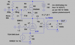
So, lets go on a budget using an E88CC. Also using the input from T:
Sure, looks nice enough. But also consider using common cathode and resistor I/U.
With a CCS loaded ECC88 you have a gain of around 30.
So for 2V out we need around 70mV RMS in. With 2mA Peak-Peak this means 100 Ohm I/U conversion resistor (to Vref) and a V Ref of 5V/3 = 1.67V. How you get the 1.67V, up to you. The DC overlaid on the ECC88 grid would be around 1.8V.
Single coupling capacitor out (maybe from the "Mu-Follower" output) and you are done.
Ciao T
So for 2V out we need around 70mV RMS in.
Ciao T
Hey T,
Why this 2V out
? My pre has a gainstage and the RIAA outputs ca 1V just as the drawn DAC-buffer. Will adjuts the Vref according to your calculations. Still I don´t get it as the 2mA setting was 2*11k where I supposed Vref should be 0,5*Vdd.
With Ug 1,3V for Ua 100V/Ia 17mA we add the 1,2V positive bias at the grid to get the 2,5V. Pa is then held at below Pamax.
Hi,
Common convention. In the olden days (does this rhyme with golden days?) before ridiculous amounts of compression where applied CD's had around 14dB Headroom. So average output would be around 0.4V. A normal MM cartridge with 5mV @ 5cm/s and the then common 34dB Phono Stage would give 0.25V average output as LP had 14dB headroom on the 5cm/s level.
Actually, Vref (in my notes) is developed across a resistor that is nominally 11K inside the DAC (hence the "Iref" label). So with two 11K resistors in series to a 5V supply Vref at the DAC becomes Vdd/3. I found boosting past 2mA lead to increased distortion, 2mA seems to be the sweet spot.
Also, the outputs should be held at a level higher than Vref.
Ciao T
Why this 2V out
Common convention. In the olden days (does this rhyme with golden days?) before ridiculous amounts of compression where applied CD's had around 14dB Headroom. So average output would be around 0.4V. A normal MM cartridge with 5mV @ 5cm/s and the then common 34dB Phono Stage would give 0.25V average output as LP had 14dB headroom on the 5cm/s level.
Will adjuts the Vref according to your calculations. Still I don´t get it as the 2mA setting was 2*11k where I supposed Vref should be 0,5*Vdd.
Actually, Vref (in my notes) is developed across a resistor that is nominally 11K inside the DAC (hence the "Iref" label). So with two 11K resistors in series to a 5V supply Vref at the DAC becomes Vdd/3. I found boosting past 2mA lead to increased distortion, 2mA seems to be the sweet spot.
Also, the outputs should be held at a level higher than Vref.
Ciao T
My pre has a gainstage and the RIAA outputs ca 1V just as the drawn DAC-buffer.
Oooops
! Should be 0,7V rms.So with two 11K resistors in series to a 5V supply Vref at the DAC becomes Vdd/3
Hey T,
This means Vref should be 1,7V when going the 2mA route. So running the DAC outputs just above this is what you recommend.
Last edited:
- Status
- This old topic is closed. If you want to reopen this topic, contact a moderator using the "Report Post" button.
- Home
- Source & Line
- Digital Line Level
- Output level of TDA1545