Hi all
Simulations reveal some issues. Using a "blameless" architecture, which as Bob says in another thread has a Miller stabilisation scheme which reduces drive impedance at high frequencies, comparison of 8 ohm load, and 8 ohm in parallel with 2.2uF, with and without a 3.3uH inductor show differences.
At 20 kHz the no-inductor solution gives almost the same output whether or not there is a 2.2uF load. Evidently this is the best option.
With an inductor and resistive only load, there is a marginally greater initial delay, which MIGHT make the sound "duller".
The really bad situation is with the inductor and 2.2uF load which shows massive "first cycle" distortion due to ringing, and continues with artificially increased signal due to ringing.
So here's the conclusion from this experiment: with a Miller architecture, which has been widely reported (mostly subjectively it has to be said) as sounding dull, but is unconditionally stable (hence an easy amplifier to use with capacitive loads) there seems to be no need for an output coil.
If an amplifier needs a coil with capacitive loads, perhaps this will degrade the apparent brightness of the amplifier (from the simulations, for those objecting to subjective terminology, this means longer delay time). The question is that these simulations were all at 20 kHz. Harmonic distortion won't be a feature. We're talking about delay times, and ringing.
It is interesting to note that the current flowing in the transistors at the first cycle peaks at 11A for a 50W amp, with the inductor, and only 9A without. Using 2N3055's in the simulator showed no difficulties. In practice the gain may be falling so far that the VAS and drivers run out of steam.
BTW this inrush current is because a continuous sinewave dumping into a capacitive load had to build up an out-of-phase current. If the current is not present, the effective load is closer to 2 ohms or so until the current has "caught up". I don't think out of phase currents are particular issue, but large ones develop large error voltages in the input stages to force the output transistors to handle them.
Moral of this story is that capacitor loads may make an amplifier overload, may trip protection circuits and generally cause havoc. If you want to run electrostatic speakers, then an alternative to an inductor is a small resistor - perhaps 0.1 ohms will do. Even JLH suggested this!
cheers
John
Attachments
The point of my recent post wasn't really to change the implementation of the output network, though I always like to eliminate a part when possible. It was more about considering the fact that the real physical networks may not match up well with what people plug into the simulations. Inductors can be very imperfect components, and much of the info here is based on simulations. A bit OT- my free Switchercad simulator can't account for the variation of series or parallel R at different frequencies. It uses fixed R and not D or Q. How does one deal with that? IMO, it has to be dealt with if the results are going to reflect reality. Here's another thought- make up ten output inductors and mount them in series with a bit of space between. Now attach the speaker wire to the tap of your choice and see if you can hear a difference. I'm going to try that, being a rather easy and inexpensive test.
Hi John and others,
I'm trying to read the implications coming from your graph.
It looks like a delay of the peaks for the inductor+capacitive load of about 3 to 5uS. It also appears that the zero crossing delay is much less, possibly 1 to 2 uS. This implies some saw tooth type distortion. What specific harmonics and relative proportions make a saw tooth?
The increase in voltage is also an obvious distortion.
When listeners report hearing a difference, what are they hearing/not hearing? Is it the peaking up (is that another word for overshoot) of the voltage or the altered harmonic structure?
What frequencies are the listeners hearing that have differences in them?
I get the impression that these inductor/no inductor effects are a high frequency phenomenon and that much of what is to be heard is above our normal hearing range.
Does that mean we are only hearing the intermodulation of the distorted high frequencies folding back down into the audible range or is our hearing system capable of dissecting the high frequencies directly and recognising that a normally inaudible signal is there to be heard?
That 11Apk into an 8ohm//C load is a surprise and supports the view that Re is not the worst resistance that a speaker presents to the amp output. Is this the first cycle effect (or similar) that Graham talks about? How long could this high peak current last in the most extreme case, 10uS or 100uS or could it happen on a sudden bass signal and extend out to 1mS? I'm thinking about false triggering of protection circuits on transients.
Hartono said:Hi Bob,
First,I don't like the nonlinearities you mentioned, that would ask for unreasonably large metal enclosure.
In voltage drive ,"perfect" output inductor + parallel resistor will change the damping factor at high frequency, this is my only real nagging, combine the impedance at HF + passive network + loudspeaker(tweeter?) thermal modulated resistance of voice coil, this should sound different compared to no inductor.
basically different damping factor sounds different, can you hear it ? I dunno
it is measurable though.
Actually I'm converting to current drive")
seriously
I agree; I don't like those nonlinearities, either. But, to be honest, I don't know how big they are and whether they are the source of audible degradation by use of a coil. Also, if those nonlinearities are there in any significant amount, I would think that they would be readily measurable by THD20 or CCIF IM. So, if we have an amplifier where all HF distortion components are down by 100 dB or more, is it safe to say that the sound is not being influenced by these output coil nonlinearities? I don't know, but I think it is a good question.
Its hard for me to get that excited about HF damping factor, especially when tube amp damping factor is typically less than 20. I just don't know. The tweeter is almost always padded down resistively in a speaker system, so this would further seem to cast doubt on HF damping factor being a source of audible degradation (also, we must always distinguish between audible degradation and slight frequency response differences).
Cheers,
Bob
Hi Andrew T
Well this is where we get into the argument about hearing distortion at 20 kHz. Since it is not possible, in the case I mentioned it would have to be the relative amplitude response that is the problem, possibly also that the additional delay causes the amplifier to sound "dull".
If we run the simulations at a lower frequency - let's say 10 kHz - then it is just possible that any distortion is audible. But the effects of the inductor will be halved compared with 20 kHz.
So far, then, it seems to me that capacitive loads are the prime candidate for the cause of the trouble, especially if these need inductors to stabilise.
The point I made about the Blameless is worth repeating -although it uses a Miller capacitor it is (or ought to be) unconditionally stable and does not (or should not) need an output inductor, even with capacitive loads.
Yes you are right in that the first cycle distortion could trip protection circuits, but again this was with capacitive loading. Projecting this to a real load, the crossover components in a loudspeaker network may well have similar effects, but most crossovers I have seen have resistors in series with capacitors and few have capacitors directly coupled across the load.
First cycle effects into capacitors may translate into "last cycle" in inductors because inductors oppose fast changes, but instead try to keep currents flowing during switch off. In this case it seems to me that the amp has to provide a discharge path for the out-of-phase currents which may stop suddenly rather than start suddenly. But there again, transient bass notes tend to cause the fast dynamic attack with a slow decay but maybe there is plenty of scope for leading/trailing edge effects as music is never sinewaves!
cheers
John
Folks would be aware that this thread is quite parallel to another on effects of output coils, so apology for repetition:
My brief comment would be that so far I could not find a reason for omitting such a coil. My own design is definitely not "unconditionally" stable without it, as shown by loop gain/phase/nfb magnitude plots. Those characteristics were chosen with other objectives in view. What people will throw at outputs of my amplifiers is outside my control, and any measure that will broaden the stability margin without affecting the sound is to me desirable.
I could not find such effects with the 6uH I am using (in parallel with 18 ohms). Any (mainly attenuation) effects start at > 60KHz. I have simulated with an equivalent typical woofer-tweeter loudspeaker (cross-over about 2,2 KHz) load, and all sorts of load variations, and sorry, I cannot find a reason for not using such a coil - neither did I in all the quite informative posts (I did learn many other things!). Lastly, my loudspeaker impedance shows an inductive component of about 80 uH at 20 KHz. An odd extra series 6 uH will affect matters how? (That 80 uH itself is most probably subject to variation with practical loudpseaker spread of more than 6 uH.)
Many output topologies are possible, some very possibly not needing a series loudspeaker inductance. But that is no proof that the use of such a coil is detrimental. Also I do not disrespect the hearing experiences of others. But there are just too many other design parameters playing a role for that in itself to be normative.
Main thing: The amplifier design should be such that such a network should not have an effect in audio.
Hi Bob,
"I would think that they would be readily measurable by THD20 or CCIF IM. So, if we have an amplifier where all HF distortion components are down by 100 dB or more, is it safe to say that the sound is not being influenced by these output coil nonlinearities? I don't know, but I think it is a good question."
As Dimitri mentioned , the magnetic field of the inductor is probably taking all kind of EMI from radiation from supply lead, etc, if the EMI is produced within the amp, mainly by the high current supply lead to the output stage, I guess this most likely to show up when highly asymmetrical waveform is used. And also from crosstalk. This can be reduced by using large enclosure, maybe too large, and proper placement. I also suspect coil is sensitive to vibration, maybe minimal effect btw , this wouldn't show up in THD without vibrating the coil.
"Its hard for me to get that excited about HF damping factor, especially when tube amp damping factor is typically less than 20. I just don't know. The tweeter is almost always padded down resistively in a speaker system, so this would further seem to cast doubt on HF damping factor being a source of audible degradation (also, we must always distinguish between audible degradation and slight frequency response differences)."
I'm not too excited about damping factor either, I'm just saying that it is sounds different, not necessarily degrading. I think we better go back to the other thread, this thread is not about audibility of output coils , sorry for going slightly out of topic guys
Just getting in a knife edge in here, while damping factor came up, that that is not very important in tweeters; they are mass controlled devices whereas low frequency drivers are velocity controlled. These have been several experiments (Scandinavian again!) where listeners actually preferred the response of high frequency drivers driven by a current rather than a voltage source.
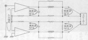
john_ellis said:an alternative
Nippon style reasoning by Ex-Stax employee Shin Kanagawa =>
Attachments
Hi Johan,Johan Potgieter said:.... My own design is definitely not "unconditionally" stable without it, as shown by loop gain/phase/nfb magnitude plots. .........
how do you derive your loop gain/phase/nfb magnitude plots and can it be done with easy to acquire/cheap equipment?
john_ellis said:Hi all
Simulations reveal some issues. Using a "blameless" architecture, which as Bob says in another thread has a Miller stabilisation scheme which reduces drive impedance at high frequencies, comparison of 8 ohm load, and 8 ohm in parallel with 2.2uF, with and without a 3.3uH inductor show differences.
At 20 kHz the no-inductor solution gives almost the same output whether or not there is a 2.2uF load. Evidently this is the best option.
With an inductor and resistive only load, there is a marginally greater initial delay, which MIGHT make the sound "duller".
The really bad situation is with the inductor and 2.2uF load which shows massive "first cycle" distortion due to ringing, and continues with artificially increased signal due to ringing.
So here's the conclusion from this experiment: with a Miller architecture, which has been widely reported (mostly subjectively it has to be said) as sounding dull, but is unconditionally stable (hence an easy amplifier to use with capacitive loads) there seems to be no need for an output coil.
If an amplifier needs a coil with capacitive loads, perhaps this will degrade the apparent brightness of the amplifier (from the simulations, for those objecting to subjective terminology, this means longer delay time). The question is that these simulations were all at 20 kHz. Harmonic distortion won't be a feature. We're talking about delay times, and ringing.
It is interesting to note that the current flowing in the transistors at the first cycle peaks at 11A for a 50W amp, with the inductor, and only 9A without. Using 2N3055's in the simulator showed no difficulties. In practice the gain may be falling so far that the VAS and drivers run out of steam.
BTW this inrush current is because a continuous sinewave dumping into a capacitive load had to build up an out-of-phase current. If the current is not present, the effective load is closer to 2 ohms or so until the current has "caught up". I don't think out of phase currents are particular issue, but large ones develop large error voltages in the input stages to force the output transistors to handle them.
Moral of this story is that capacitor loads may make an amplifier overload, may trip protection circuits and generally cause havoc. If you want to run electrostatic speakers, then an alternative to an inductor is a small resistor - perhaps 0.1 ohms will do. Even JLH suggested this!
cheers
John
Hi John,
These results are interesting on a couple of levels, but I do have some questions.
Am I correct in understanding that you did not include a damping resistor across the 3 uH coil? That can make a very big difference, and I would never recommend eliminating that resistor.
I'm pleasantly surprized that the Miller architecture you simulated was stable into 2.2 uF, but I'm not sure that is always going to be the case. It may depend a lot on the specific implementation and compensation. It may also be unstable into a smaller capacitive load.
Cheers,
Bob
Andrew,
I was talking mainly simulation with Spice. Where I did check reality I did it with cumbersome scope input/output point-by-point plotting! It would be possible to plot directly with some of the analysers available (and I presume pc software), but alas, I am not the proud owner of such luxuries (yet). Local economical situation blah blah ...., not to go into politics. I still do the "spadework way" occasionally just to verify that reality is not too far off the simulation. (I did until some time ago still have contacts at the lab where I worked to use their instruments, but erstwhile colleagues, like myself, have retired, etc. )
)
So I must regrettably give you a mundane reply.
Regards.
I was talking mainly simulation with Spice. Where I did check reality I did it with cumbersome scope input/output point-by-point plotting! It would be possible to plot directly with some of the analysers available (and I presume pc software), but alas, I am not the proud owner of such luxuries (yet). Local economical situation blah blah ...., not to go into politics. I still do the "spadework way" occasionally just to verify that reality is not too far off the simulation. (I did until some time ago still have contacts at the lab where I worked to use their instruments, but erstwhile colleagues, like myself, have retired, etc.
)So I must regrettably give you a mundane reply.
Regards.
I just read Bob's comments to John's post, which arrived while I was posting (phase delay/group delay in posts as well?)
My experience was also having difficulties with the C.dom Miller compensation alone, to the point where I had to dispense with that as the main pole. I got along rather better with lead compensation and a pole elsewhere.
I must again refer to the interesting article by John Ellis in EW a few years ago regarding phase lead input lag compensation. I implemented it and had quite more success with that than the classic style. I suppose it depends on the circuit (mine deviates somewhat from the classsic), but that was what worked for me.
Regards.
john_ellis said:Hi all
Simulations reveal some issues. Using a "blameless" architecture, which as Bob says in another thread has a Miller stabilisation scheme which reduces drive impedance at high frequencies, comparison of 8 ohm load, and 8 ohm in parallel with 2.2uF, with and without a 3.3uH inductor show differences.
At 20 kHz the no-inductor solution gives almost the same output whether or not there is a 2.2uF load. Evidently this is the best option.
With an inductor and resistive only load, there is a marginally greater initial delay, which MIGHT make the sound "duller".
The really bad situation is with the inductor and 2.2uF load which shows massive "first cycle" distortion due to ringing, and continues with artificially increased signal due to ringing.
So here's the conclusion from this experiment: with a Miller architecture, which has been widely reported (mostly subjectively it has to be said) as sounding dull, but is unconditionally stable (hence an easy amplifier to use with capacitive loads) there seems to be no need for an output coil.
If an amplifier needs a coil with capacitive loads, perhaps this will degrade the apparent brightness of the amplifier (from the simulations, for those objecting to subjective terminology, this means longer delay time). The question is that these simulations were all at 20 kHz. Harmonic distortion won't be a feature. We're talking about delay times, and ringing.
It is interesting to note that the current flowing in the transistors at the first cycle peaks at 11A for a 50W amp, with the inductor, and only 9A without. Using 2N3055's in the simulator showed no difficulties. In practice the gain may be falling so far that the VAS and drivers run out of steam.
BTW this inrush current is because a continuous sinewave dumping into a capacitive load had to build up an out-of-phase current. If the current is not present, the effective load is closer to 2 ohms or so until the current has "caught up". I don't think out of phase currents are particular issue, but large ones develop large error voltages in the input stages to force the output transistors to handle them.
Moral of this story is that capacitor loads may make an amplifier overload, may trip protection circuits and generally cause havoc. If you want to run electrostatic speakers, then an alternative to an inductor is a small resistor - perhaps 0.1 ohms will do. Even JLH suggested this!
cheers
John
John,
Thanks for this interesting post. But something isn't quite clear to me. The effects of the coil with cap load are, if I read you correctly, twofold: one, it causes delay at high frequencies, two, it causes increased signal level (at the speaker, not at the amp) in particular at the initial cycles. Are you saying that the delay could cause 'dullness'? Wouldn't the initial incease in level at high frequencies cause more brightness? Could not the net effect be more brightness?
Jan Didden
Hi Bob
There was a 10 ohm damping resistor in parallel with the 3.3 uH coil.
I agree, undamped coils certainly would be troublesome.
Whenever I use a "blameless" amplifier configuration I choose the input emitter decoupling resistors to be rather larger than the 100 ohm usually used; in addition the input stage current is increased; and the dreadful Miller capacitor need only be quite small (but has to be larger than about 10 pF or it is swamped by variations in Cjc of the VAS). This ensures that there can be no cut-off in the input stage for any input within the normal limits. Distortion is a little worse than the usual 0.003% or so, and rises above 10 kHz, but nevertheless it is unconditionally stable if using a 4 MHz output pair (eg MJ21193/4) and a unity-gain (closed loop) of 10 MHz, which still surprises me at being stable!
Hi Jan
I think that the audible effects will be something which may cause "listener fatigue". Sorry to use subjective terms, but when the initial cycle starts, and is larger (at the speaker) than the following cycles, I believe the sound will be somewhat "artificially bright" if anything. In other words, both delayed and bright at the same time!
I've not listened to such an amp. with a 2uF load. One amp I have heard sound like this description is the dual-slope Miller types where the Miller capacitor is filtered to give a higher open loop gain which reverts to 6 db/octave before hitting the unity gain line.
I've often puzzled by the term listener fatigue in early designs. Does anyone have a view?
My twopennorth is that it is simply arising from intermodulation products - amplifiers which don't have low enough distortion create harmonics which don't belong, and the brain is trying to remove the sound because it "knows" instruments should n't have them...
But, unless several sets of transistors are used in parallel I suspect that real amps will distort wiht resonant load (coil+capacitor) because of the huge current inrush.
From this point of view, coils are best avoided, but it is not established that they are audible per se.
cheers
John
john_ellis said:I've often puzzled by the term listener fatigue in early designs. Does anyone have a view?
My twopennorth is that it is simply arising from intermodulation products - amplifiers which don't have low enough distortion create harmonics which don't belong, and the brain is trying to remove the sound because it "knows" instruments should n't have them...
John
I am going to stick my neck out here:
Most (all?) naturally produced sounds have an harmonic spectrum where each of the higher order harmonics is smaller in amplitude than the previous harmonic. This doesn't necessarily aply to the first few harmonics which give instruments their character.
In electronic devices each high order harmonic can be equal or even higher in level than the previous lower frequency one and the harmonics often continue into fairly high orders (i.e. 10th, 11th and higher).
This un-naturalness contrasts with how the same instruments or voices sound naturally in essence providing a white noise sheen on top of the music.
If you've ever driven truly long distances, the wind noise adds to stress and makes you tired.
The brain is very good at recovering coherent sounds from a noisy background, but I think it takes work. Eventually the effort overcomes the pleasure of the music.
I'm not really prepared to defend this idea, it seems plausible to me though.
output coils and caps
Hi John,
Are you saying that your simulation reveals no oscillation with a true (i.e. ESR=0) capacitive load of 2.2uF? This really amazes me. I have run hundreds of sim's on many different topologies, but with 2.2uF, I always got troubles. Are you sure your models are okay, in particular regarding the O/P transistors? Did you have also simulated the lead inductance of the O/P devices (ca. 10nH/cm)? The latter makes quite a difference!
Cheers,
john_ellis said:Hi all
Simulations reveal some issues. Using a "blameless" architecture, which as Bob says in another thread has a Miller stabilisation scheme which reduces drive impedance at high frequencies, comparison of 8 ohm load, and 8 ohm in parallel with 2.2uF, with and without a 3.3uH inductor show differences.
At 20 kHz the no-inductor solution gives almost the same output whether or not there is a 2.2uF load. Evidently this is the best option.
[snip]
cheers
John
Hi John,
Are you saying that your simulation reveals no oscillation with a true (i.e. ESR=0) capacitive load of 2.2uF? This really amazes me. I have run hundreds of sim's on many different topologies, but with 2.2uF, I always got troubles. Are you sure your models are okay, in particular regarding the O/P transistors? Did you have also simulated the lead inductance of the O/P devices (ca. 10nH/cm)? The latter makes quite a difference!
Cheers,
- Status
- This old topic is closed. If you want to reopen this topic, contact a moderator using the "Report Post" button.
- Home
- Amplifiers
- Solid State
- Output coil on power amp...