Wavebourn said:Why he insists on a non-inductive resistor in cathode?
Who invented the first such fashion?
I have no idea. You should email him and ask.
Because, I don't think neither you or me, have enough knowledge to tell.

His email can be found here (and a lot of other stuff):
Illuwatar Homepage MAIL ME
------------------
Nevertheless, this headphone amplifier setup is built and use by several.
6922 + 6AS7 ( 6AS7G ) in SE OTL configuration, with this circuit as model.
IMAGES - Lots of other E88CC + 6AS7 Headphones Amplifiers
.. using this nice 6AS7 Dual Power TRIODE, for their head amps
lineup
Geek said:Hi Andy,
Output stage, just with different tubes. Original design had a choke and I tried a choke, resistor and CCS and never got it stable... on a breadbord at least
HI.
What form did the instability take ??
Andy
Hi Andy,
300KHz rail-to-rail squarewaves, dropping to 10Hz pulses with an 8 ohm load attached.
Had super risetimes on those pulses though
poynton said:
What form did the instability take ??
300KHz rail-to-rail squarewaves, dropping to 10Hz pulses with an 8 ohm load attached.
Had super risetimes on those pulses though
Finally I´ve started my long awaited SE OTL project.
Each channel will employ 5 x 6C19, each running at about 110mA and 80V (or so).
0,55A total bias should give 1,2W rms into 8 ohms load, how Rosenblitz manages to get 1,5W out of four tubes is a mystery to me.
Each tube will have a 4,7 ohm cathode resistor before they connect to the cathode choke (600 turns of 0,45mm wire on a 45VA transformer core with ~0,5mm airgap).
The driver stage will be a CCS loaded PC86 with the feedback connected to the grid (something like 2,2k from input to grid and 10k from grid to output). There will also be a Jfet buffer on the input to drive the low impedance feedback network.
The circuit is fairly simple, but the PSU will be a mess. I need 80V 1,1A for the output stage, 31V 2A or 12,6V 5A for the 6C19 filaments, 200V 25mA for the driver stages, 8V 300mA for the PC86 filaments and +-12V 10mA for the input buffer (and negative grid bias for the output stage).
To increase the lifespan of the cathodes I want a 1 minute delay on the 80V and 200V rails.
To make my life easier I´ve decided to build the signal circuitry first in a separate chassis and then start with the PSU on a breadboard.
I have a preference for separate power supplies, they can be hidden behind a subwoofer or something and avoiding AC in the amp chassis is a very good thing if you don´t like hum.
SE OTL
May I ask, Why S.E. OTL?.....
Lots of tubes, Lots of heat, lots of waste energy, can be high distortion, and problems of Instability apparently....
Ive an OTL, but not an SE, Its based on the Circlotron, with the 6C33C as the 'power-bottles' One each 'side' running 75-100mA idle-current, at 195-200V.
In comparison to the SE diagram which is delightfully simple, My OTL is an absolute nightmare, employing 'diff-amps' etc to control O/P impedances, as well as the split circlotron supplies and the other rails for the signal and diff-amp tubes, but does work well, and can achieve 50W output power and reasonably reliable so far.
Why SE OTL...? Maybe is like, --Because its there?
Why S.E. OTL?.....
Building a "normal" OTL amp would involve paying for a huge power transformer, several quite expensive power tubes and a bank of PSU caps.
Building an SE OTL similar to Rosenblitz´s kit would be an "junkbox adventure" for me, I have pretty much everything except the filament transformer and some of the caps and resistors.
I´ve had amps in the 1W range playing in my system before and lack of power has not been a problem.
The efficiency will be even lower than the 4-5% in my Son of Zen, but tubes and transformers doesn´t require heatsinks so the 200W (or so) of losses is no problem.
Why SE OTL...? Maybe is like, --Because its there?
That is reason enough for me. I have got two BIG chokes 2HY at 2 AMPS, each about 50 lbs, a box full of 6336A's, and a 1KW isolation transformer, just not enough time or bench space! Some day. It's pretty far down on the list of projects though.
2HY at 2 AMPS, each about 50 lbs, a box full of 6336A's, and a 1KW isolation transformer
How can such a thing be "pretty far down on the list"???
I have far too many projects, an assembly manual and website update to finish, and then there is this reality:
The likelihood of making enough power to see daily use in my work room with 86db speakers is very low.
The WAF of something large, probably ugly, and that weighs as much as she does, is surely low enough that it would rarely spend time with the 96db speakers in the living room. Only when she is not home. She is out of town for 2 weeks, so there is currently 3 amplifiers on the table, and I will drag the 845SE out tonight!
Yes it would be different, cool, and might even sound good, but for now there are more practical projects that need finishing. So this one is down there with the 200 watt SE guitar amp. That doesn't mean that I won't prototype something to see if it works when I get caught up on everything else.
excellent Fulling! Keep us updated with your project. I have 16 pieces 6c19 and I was giving up the hope that I would find an Otl schematic for them. I have owned only one tube amp for a short period of time, a long time a go, but still I am very certain that OTL would yield great results in my system (16ohm, 98db/m).
Tubelab: Every man should, once in life, build an amp that weights more than his wife!
But I understand, I know how it feels to have too many projects in the pipeline. The constant stress has become a part of my life...
JPPP: With 16 ohm 98dB speakers OTL might definitely be the way to go! With that kind of load you might even get useful results with 3 or perhaps even 2 output tubes, but more would be better of course.
Ok, I should have posted some schematics here days ago but nothing has happened. I usually do such things when I work late, but there´s been a lot to do at work lately.
Another reason why I havent come up with any schematics is that I for a short while forgot about the whole SE OTL thing and started reading up on various PP OTL projects instead.
I´m sure an inverted Futterman with 6 x 6C19 per channel would be worth a try, but all the extra stuff required to drive the output tubes properly finally got me back on the SE track.
I´ve been digging around in my junkbox a bit and came up with some interesting transformers, with a little luck and a shoehorn I might get everything into one chassis after all.
Not that I´m too fond of having big power transformers just inches away from low-level circuitry, but good connectors to use between PSU and amp are expensive...
With one 12V 50VA filament transformer per channel available, why not go "The full monty" and use six output tubes per channel?
Output power increases in square with the quiescent current, so every extra fraction of an Ampere is most welcome in a project like this where current is the limiting factor.
So: 2 x 12V 50VA for the output tube´s filaments.
1 x (2 x 36V) 225VA for the output´s plate voltage.
1 x power transformer from an old tube radio for the drivers
2 x cathode chokes
12 x output tubes
2 x input tubes
<10 x 680uF 160V Rifa caps
All this on a 10 x 16" alu sheet. Wish me luck!!
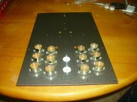
It´s been a while since I did anything to this amp, I´ve been working on an 807 SE amp for my brother and gathered parts for a couple of big SE DHT projects. I did order some parts a couple of days ago though, so perhaps some initial testings can be done in a not so distant future.
I´ll start with the output stages, when they operate as intended I´ll work my way towards the input stage.
No schematic yet.
I´ll start with the output stages, when they operate as intended I´ll work my way towards the input stage.
No schematic yet.
Update: The 12 x 6S19 OTL is abandoned due to heater and PSU issues.
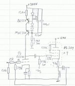
A new design incorporating 8 x PL504 is in progress, the 27V 300mA heaters are much easier to deal with as they can be connected in strings and fed with DC.
I have a big toroid transformer that is very suitable for this, it has one 77V 5A winding and two 9,5V 2A windings.
My idea is to rectify and CLC-filter the 77V to get just over 100VDC for the heaters and then stack the (separately rectified) 9,5V windings on top of this to get about 125VDC for the output stage.
Aside from this three more voltages are required: heater and plate voltage for the input tube and a negative grid voltage for the output stage. No problems, any little tube radio transformer should manage this.
- Status
- This old topic is closed. If you want to reopen this topic, contact a moderator using the "Report Post" button.
- Home
- Amplifiers
- Tubes / Valves
- OTL SE - Help Wanted with Idea