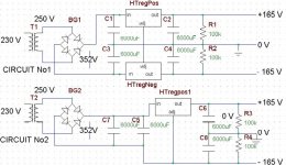
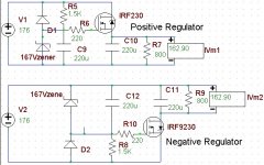
I’m going to build the famous 6C33 OTL design by Mr. Ciuffoli and I’m planning to use a regulated HT for both the drivers and the final stages. So if you notice on the schematic the 250VAC from the transformer goes to the rectifier bridge and we have about 352V DC. Now we have two possibilities Circuit 1 or 2. Which one you think is the best to use? Please note that I already have in my hands these 6000uF capacitors. Also in the next message I will send the regulator circuit Positive and Negative with the discrete parts.
Thanks in advance
Chris
Thanks in advance
Chris
Attachments
Hi,
Maybe not the answer you are looking for but I suggest that you build the OTL amp without regulators, it works well if you use good components, (especially the PS caps). In my OTL that is similar to the Ciuffoli circuit I use 2 x 5500uF as only filtering for the power tube supply, it works very well. For B+ to the driver I use CRC with 100uF + 100uF and then one RC stage with 220uF to feed the input stage, (SRPP).
Regards Hans
Hans,
I was thinking of using the regulated PS because I will use this amp with a set of back loaded horns using FE208ES units with total sensitivity of about 100dB, so as you can see I dont like to have any irritating HUMMM on the speakers. Also I think that in case I will use this PS, there is no need of any chokes because the ripple of the voltage will be very very small, finally the cost and the weight of the chokes also is importand.
I was thinking of using the regulated PS because I will use this amp with a set of back loaded horns using FE208ES units with total sensitivity of about 100dB, so as you can see I dont like to have any irritating HUMMM on the speakers. Also I think that in case I will use this PS, there is no need of any chokes because the ripple of the voltage will be very very small, finally the cost and the weight of the chokes also is importand.
so as you can see I dont like to have any irritating HUMMM on the speakers.
Yes I can appreciate that as I am using Lowther horns myself. My amp gives 0.4mV Pk-Pk noise and hum which gives signal to noise ratio of >100dB, this without using any chokes and no regulators only caps, I can not hear any disturbing hum at all using my Lowther Fidelio horns which have about ~100dB sensitivity so I think it is quiet enough.
Regards Hans
Regulation or no regulation ....
Just to cast my vote here, my impression, from direct experience and otherwise, is that power supply regulation benefits the overall sound and fidelity of the amplifier stage in question, including that of the output stage. Regulation can be complicated, surely, but so are many a beneficial thing such as, say, women, which can be seen to benefit life.
Just to cast my vote here, my impression, from direct experience and otherwise, is that power supply regulation benefits the overall sound and fidelity of the amplifier stage in question, including that of the output stage. Regulation can be complicated, surely, but so are many a beneficial thing such as, say, women, which can be seen to benefit life.
Hi,
Generally speaking I'd agree but let's look at the facts here:
This OTL runs class AB1.
Max power into 8 Ohm load is about 25W tops for this design.
Speaker has ~ 100 db/W/m effeciency.
This means that for all intents and purposes the amp is likely to spend most of its life outputting 1 to 10W at most.
Regulating the B+/- of an OTL amp isn't simple and as far as hum is concerned, most of it can effectively be taken care of with decent filtering and careful layout.
Moreover, this is a PP amp so a huge chunk of the hum will effectively be cancelled out anyway.
In practice, a good OTL amp can be as quiet as any other topology.
In fact, I often find them quieter than most others, perhaps because more attention is paid to the design and layout. Who knows.
As for choke filtering the main PS, great idea but where on earth are you going to find such animal?
The Ciuffoli design can benefit from a regulated driver PS IMO but it will add to TOC.
It would however be a great idea to study the circuit and see how we could improve on it by sticking our heads together...
Regarding the PS cap bank; my own OTL uses two banks of 2*10.000 µF/200V. I suppose Mr. Joule would be proud of me...
Cheers,
power supply regulation benefits the overall sound and fidelity of the amplifier stage in question, including that of the output stage.
Generally speaking I'd agree but let's look at the facts here:
This OTL runs class AB1.
Max power into 8 Ohm load is about 25W tops for this design.
Speaker has ~ 100 db/W/m effeciency.
This means that for all intents and purposes the amp is likely to spend most of its life outputting 1 to 10W at most.
Regulating the B+/- of an OTL amp isn't simple and as far as hum is concerned, most of it can effectively be taken care of with decent filtering and careful layout.
Moreover, this is a PP amp so a huge chunk of the hum will effectively be cancelled out anyway.
In practice, a good OTL amp can be as quiet as any other topology.
In fact, I often find them quieter than most others, perhaps because more attention is paid to the design and layout. Who knows.
As for choke filtering the main PS, great idea but where on earth are you going to find such animal?
The Ciuffoli design can benefit from a regulated driver PS IMO but it will add to TOC.
It would however be a great idea to study the circuit and see how we could improve on it by sticking our heads together...
Regarding the PS cap bank; my own OTL uses two banks of 2*10.000 µF/200V. I suppose Mr. Joule would be proud of me...
Cheers,
Hi,
Regarding regulators I don't think they are trivial to design as to not influence the sound as the power supply can be seen as being more or less, (depending on the PSRR) part of the signal path, therefore I try to avoid them as much as possible. Anyway I don't go trough the extra work to use tubes just in order to listen to a solid state regulated power supply.
In my own setup I only use regulators, (tube based) in my preamp as I believe this is an efficient way to get low hum and noise levels, a preamp is a class A amp with normally decent PSRR so I think a regulator can be accepted there.
Anyway for an OTL amp of the type discussed here there is no need to use regulators in order to get it quiet, what is needed is some good PS caps, a good physical layout and some thinking when doing the wiring, especially the grounding.
Regards Hans
Regarding the PS cap bank; my own OTL uses two banks of 2*10.000 µF/200V. I suppose Mr. Joule would be proud of me...
Hi, Frank -
That's about where I'm at with my DC coupled prototype - I started with 2 7500 uf's for each supply polarity, then changed the ones after the series chokes to 12,000 uf, which puts me at a total of just under 20,000 a side. Maybe I'll really go over the top and try dropping in some of those new ultra high CV product 'lytics some day.
I recently replaced the AC supply 6A slow-blow fuse with a 7A to handle some high energy rock, but then I blew the 7A, too. I don't want to go too high here, but I might try 8A. Actually, I should replace the 700VA toroid which powers the output heaters and supply rails with a 1 KVA core because it eventually gets to about 30-40C above ambient which is a bit much, but going with a bigger tranny would allow me to bias the amp further into class A which I know from past experience can significantly drop the distortion - and after running 16 years with some of the original 6as7g's and still pulling enough current to pop 7A supply fuses, I don't really think output tube lifespan shortening with higher bias is a major issue anymore, although I still have over a hundred NIB russian and NOS 6as7g's bought just in case back in the days when they were going for a buck or two
tubetvr said:Regarding regulators I don't think they are trivial to design as to not influence the sound as the power supply can be seen as being more or less, (depending on the PSRR) part of the signal path, therefore I try to avoid them as much as possible.
Yes, the power supply is a series component in the signal path. A PSU regulator is likewise in series with the signal path, and I agree a regulator must therefore be designed competently. But a regulator, leaving aside SS devices, is but a tube, and tubes sound good, don't they? I mean, I'd personally rather listen to a tube than, among other things, grunge produced by my neighbour's electrical system which, because hooked into the power grid we share (not to mention everything else on that grid, including miles of aluminum wire and overstressed, buzzing transformers etc) is also, at least to some degree, in series with the signal path. I also think regulating PSU output Z benefits overall PSU behaviour.
It is not trivial but of course possible to build a tube regulator giving at least 0.8A continous current which is what is needed to produce 25W at 8 ohm load. Any active regulator added to an amp is an additional design problem that need to be solved, why do that if it is not needed?
You don't need a regulator to remove hash and other disturbances from the power grid, it can be done by careful selection of transformers and filtering components.
Regards Hans
I'd personally rather listen to a tube than, among other things, grunge produced by my neighbour's electrical system which, because hooked into the power grid we share (not to mention everything else on that grid, including miles of aluminum wire and overstressed, buzzing transformers etc) is also, at least to some degree, in series with the signal path.
You don't need a regulator to remove hash and other disturbances from the power grid, it can be done by careful selection of transformers and filtering components.
Yes that is good in the case it is needed but my conclusion is that it is not in this case.I also think regulating PSU output Z benefits overall PSU behaviour.
Regards Hans
fdegrove said:As for choke filtering the main PS, great idea but where on earth are you going to find such animal?
Where you get it anyway, you wind it. At low voltage you only need a few mH.
Regarding the PS cap bank; my own OTL uses two banks of 2*10.000 µF/200V.
I'd say
, but you were expecting that anyway. 
Tim
Hi,
A few Henry at a couple of amps is more like it.
An uninformed opinion on something you don't know about?
Cheers,
At low voltage you only need a few mH.
A few Henry at a couple of amps is more like it.
I'd say
An uninformed opinion on something you don't know about?
Cheers,
Thanks all of you for the time. But please lets stay focus on my main question regarding which of these topologies whould you choose between circuit 1 and 2. Now regarding the choose of tubes or mosfet as active element on the PS section is another thing, maybe Im will use a 6080, 6AU6, OA2 setup instead of a mosfet and a diode zener. So please lets accept the regulator thing as a tree wire box doing the same job even if it is build with mosfet or tubes.
Thanks again all of you
Chris
Thanks again all of you
Chris
6080 is not enough in this application, the amp draw 0.8A continouos current at full output power which a 6080 can't handle.
I still don't understand why you want to use a regulator when you can get low enough hum, (that means not hearable) without it but anyway that is your choice.
If you want to use a regulator it must be designed for 0.8A continous current and I advice you to make it more stable than in your circuit, using Zeners at high voltage gives very bad temperature drift and voltage shift depending on Zener current so you will have an output voltage that is not constant and varies with temperature and load.
I would build a closed circuit regulator using a high speed opamp with the circuit carefully tuned for good high frequency response.
Regards Hans
Hans,
Item No1.
P=V x I =I x R x I (For P=25 W, R=8 Ohm) => I=1,77A rms Passing through the 8 Ohm load, producing 25 W power, Right?
So how you calculate 0.8 A continous current?
Also I do believe that the capacitor bank can give the extra peak current to the amplifier when he will ask for it.
Item No2.
In case of these amount of current the 6080 is to small to do the job I will agree with you. Maybe the use of another 6C33 as a pass element in the PS regulator would do the job (this was my first idea) but once again, see can't handle the 1.77 A (or 0.8 A) through her.
Item No3.
In case of using the mosfet idea now , a mosfet can handle easy lets say 2A current with about 30 Volts between drain and source pins. The thermal noise produced by the zeners and variation of the constants can be reduced by using many small voltage zeners in series in order to create a high voltage zener with better overall characteristics.
What do you all think about it?
Thanks
Chris
fdegrove said:
A few Henry at a couple of amps is more like it.
Let's see here.
Start with a typical rule of thumb: +300V 100mA power supply. You agree in other threads that a CLC filter such as 50uF > 10H > 100uF has acceptable attenuation. Let's look at how much.
A typical equation for 60Hz hum is 1900 * A / C, with A in amperes and C in microfarads. (Note that this equation factors out voltage.) So hum before the choke is around 3.8Vrms. The following choke and cap form a voltage divider to the AC signal of 2 * pi * 10H * 120Hz = 7540 ohms for the choke and 1 / (2 * pi * 0.0001F * 120Hz) = 13 ohms. Vo = V * R2 / (R1+R2) so 3.8V * 13ohm / (7540 + 13)ohm = 0.0065V, 6.5mV rms - negligible (0.002%).
Now let's scale it around a bit. Let's try it with the same power level of 30W, but at a tenth the voltage - 30V - and tenfold the current - 1A. A good figure for a similar SS amp.
Now your first instinct is, current is higher so capacitance should rise. Voltage is lower, but what does that affect? Inductance, and I can show it mathematically.
First, let's make the reasonable assumption that you want the same energy storage - E = (1/2) * C * V^2 --> 0.5 * 0.00015F * (300V)^2 = 6.75J. (I'll get to the inductor's energy later.) A little algebra and we have C = 2 * E / V^2 --> 2 * 6.75J / (30V)^2 = 0.015F total for the lower voltage. With the same arrangement, this is 5000uF first and 10,000uF second. This yields 1800 * 1 / 5000 = 0.36Vrms ripple, a bit low actually and I would never recommend 5000uF/ampere because I'm nice to my transformers. This indicates a nonlinear relation (or rather, less so than the squared relation I used above), but we will continue for the sake of argument.
The ripple reduction factor above was 3.8 / 0.0065 = 585 (-55dBV). The same factor applied here will net a hum of 0.62mV (again, 0.002% of the supply - negligible). To obtain this reduction with the second capacitor being 10mF = 0.13 ohms, the inductor must be (again, some algebra) R1 = (V * R2 / Vo) - R2 = (0.36V * 0.13ohm / 0.00062V) - 0.13ohm = 75 ohms reactance. Xl = 2 * pi * F * L so L = Xl / (2 * pi * F) = 75ohm / (2 * pi * 120Hz) = 0.1H = 100mH. Now I said at the beginning that I'd get back to the magnetic rather than electric field's energy: the equation is (very similar to the capacitor, as you might expect) E = (1/2) * L * I^2 = 0.5 * 0.1H * (1A)^2 = 0.05J. The original circuit stored 0.5 * 10H * (0.1A)^2 = 0.05J. They are equivalent in performance in every way, including power, except for the different voltage and current.
(Note that the key to the above discussion is expressing hum as a percentage of the supply voltage. You'll never notice 100mV on your 845 plate, but you would be deafened by it in a SS phono stage (with nil PSRR).)
You can take a standard quality power supply outline of power equal to the OTL's (what, 180V 2A? = 360W) and scale the voltage and current, and thus capacitor and inductor values, appropriately; or you can take such an example as above (300V 100mA) and simply tweak the voltage and current individually. Pretty simple with ratios and observing the squares where needed.
Oh, one final point of discussion - 1H 1A would go for 212V 1A (212W at 0.002% ripple = 4.2mV), which quite honestly is uselessly low any way you cut it (a.k.a., your circuit must really suck eggs if you need that much filtering).
An uninformed opinion on something you don't know about?
A good reason why you should stay away from sound scientific persuits like electronics.
Tim
- Status
- This old topic is closed. If you want to reopen this topic, contact a moderator using the "Report Post" button.
- Home
- Amplifiers
- Tubes / Valves
- OTL PS question!!