"Telegraphic"?
Many valve data sheets specify a maximum DC resistance between heater and cathode of something like 20k, with specific exceptions (e.g. LTP). Those which don't specify it are almost certainly assuming a grounded heater chain, as was the normal practice in the valve era. No valve electrode should ever be left floating.
Many valve data sheets specify a maximum DC resistance between heater and cathode of something like 20k, with specific exceptions (e.g. LTP). Those which don't specify it are almost certainly assuming a grounded heater chain, as was the normal practice in the valve era. No valve electrode should ever be left floating.
"Telegraphic"?
I just meant it was a little economical with the words
")
Thanks for the clarification.
Chris
In the heater design I uploaded there is no DC connection of the filament supply to ground in order to relieve voltage stress between the filaments and the cathodes of the tubes. Nor is it an absolute that such a connection is required I have built and seen many amps without such a connection and they have worked for years without any issues. however a AC connection is supplied in order to help minimize high frequency parasitic oscillation from these same elements which can cause considerably more damage. I have this same exact set up in an OTL amp that has been work for 6 years with the same tubes.
Which is why my original lose of brain power made me question my original idea at the start of the thread on such a heater supply using mixed tubes and mixed voltages as such a setup is clearly shown in my second upload and has worked fine for years so I was just wondering why it could not work the way I showed in my originally uploaded schematic is this one works.
Which is why my original lose of brain power made me question my original idea at the start of the thread on such a heater supply using mixed tubes and mixed voltages as such a setup is clearly shown in my second upload and has worked fine for years so I was just wondering why it could not work the way I showed in my originally uploaded schematic is this one works.
No DC connection is just as likely to cause voltage stress, as there is nothing (apart from heater-cathode insulation, capacitor or transformer insulation breakdown) to stop the heater from acquiring an electric charge. Maybe it is daft of me to assume that valve manufacturers understand their own products.
Heaters may, on rare occasions, be the feedback path for RF parasitic oscillation. If so, you would need more than just one cap to stop this.
Heaters may, on rare occasions, be the feedback path for RF parasitic oscillation. If so, you would need more than just one cap to stop this.
I
Which is why my original lose of brain power made me question my original idea at the start of the thread on such a heater supply using mixed tubes and mixed voltages as such a setup is clearly shown in my second upload and has worked fine for years so I was just wondering why it could not work the way I showed in my originally uploaded schematic is this one works.
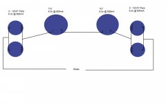
I think it was already more or less addressed in previous responses, but the crucial thing is that each tube in a single heater chain should require the same current. A 12AX7 with series-connected heaters requires 150mA (at 12.6V), a parallel-connected 12AX7 requires 300mA (at 6.3V), and a 7n7 requires 600mA (at 6.3V). So although the individual "desired" voltages all add up to what you want, the currents are wildly different, and so the actual distribution of voltages will be way off what is wanted.
You could get the currents right if you paralleled both 12AX7 tubes so that they need 600mA total (at 6.3V), and then connect in series with the 7n7. But then you'd need something like a 12.6V supply instead. (And the zener trick I mentioned before would be a good idea, since very likely the 12AX7 tubes would heat up faster than than the beefier 7n7.)
Of course, if the tube line-up you mentioned is for just one channel, so that actually you need another set for the other channel too, then chaining the other set in the same style, and then chaining the two sets in series, you would get to the 25V of the power supply you mentioned in you original posting.
Chris
No DC connection is just as likely to cause voltage stress, as there is nothing (apart from heater-cathode insulation, capacitor or transformer insulation breakdown) to stop the heater from acquiring an electric charge. Maybe it is daft of me to assume that valve manufacturers understand their own products.
Heaters may, on rare occasions, be the feedback path for RF parasitic oscillation. If so, you would need more than just one cap to stop this.
Im gonna disagree with you here and leave it at that.
I think it was already more or less addressed in previous responses, but the crucial thing is that each tube in a single heater chain should require the same current. A 12AX7 with series-connected heaters requires 150mA (at 12.6V), a parallel-connected 12AX7 requires 300mA (at 6.3V), and a 7n7 requires 600mA (at 6.3V). So although the individual "desired" voltages all add up to what you want, the currents are wildly different, and so the actual distribution of voltages will be way off what is wanted.
You could get the currents right if you paralleled both 12AX7 tubes so that they need 600mA total (at 6.3V), and then connect in series with the 7n7. But then you'd need something like a 12.6V supply instead. (And the zener trick I mentioned before would be a good idea, since very likely the 12AX7 tubes would heat up faster than than the beefier 7n7.)
Of course, if the tube line-up you mentioned is for just one channel, so that actually you need another set for the other channel too, then chaining the other set in the same style, and then chaining the two sets in series, you would get to the 25V of the power supply you mentioned in you original posting.
Chris
I understand where you are coming from but again here is the real world fact. That second schematic I posted in the thread has tubes of both varied voltage and current and it works fine and has worked for years that way. This afternoon I turned her over and powered it up check voltage and current consumption at varied points and the start pull down different was slight with no extreme hogging from any tube. So I get what the books say but I have it working here in my living room feel free to stop on by
And since I started this thread I have located many other heater arrangments that work the same in both DC and AC arrangments with varied tubes and volatges.
So why does it work on my second posted schematic? Is it the fact that the 12XX7 tubes are in their own line parallelled to the others? What?
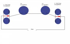
Yes, that is the crucial difference. In a given heater chain, the same current flows through each element in the chain. So if you have a mixture of tubes requiring different currents in the same chain, then some will be getting too much, and some too little. In your second schematic, each chain contains tubes whose required heater currents are identical. The fact that other chains are comprised of tubes with a different current requirement is immaterial, since each chain operates independently of all the others.
Chris
than this should work would you agree?
Attachments
The last schematic you posted should work in principle, yes. But mixing parallel/serial heaters is still not recommended, though it works theoretically - just for one example, if one of the paralleled 12AX7 fails, it will probably lead to subsequent destruction of the second 12AX7 in that pair.
Greetings,
Andreas
Greetings,
Andreas
The last schematic you posted should work in principle, yes. But mixing parallel/serial heaters is still not recommended, though it works theoretically - just for one example, if one of the paralleled 12AX7 fails, it will probably lead to subsequent destruction of the second 12AX7 in that pair.
Greetings,
Andreas
could add a small LED on the 12ax7's on the load side so if the heater dies than the led light goes out
than this should work would you agree?
Yes, that should work. As I mentioned before, it might be a good idea to put power zeners of appropriately chosen voltage across each of the banks of 12AX7 tube heaters, to prevent the voltage across them rising too high at switch-on. (I am suspecting that the 7n7 tubes will tend to heat up considerably slower than the 12AX7 tubes, and that therefore in the first few seconds the 12AX7 heaters would tend to get a disproportionate share of the voltage.) 6.8V is a standard zener voltage, so that might be suitable. The zeners would also protect against a failure of of one of the paralleled 12AX7's.
It would also be good to check that in the steady state, after they have all warmed up, that the voltages across each 7n7 and 12AX7 bank really are about right.
Series-connected heaters may not be the most highly recommended way of doing things, but if it works, then why not? I've got away with it so far, for a set of fairly disparate tubes hooked up in a chain running from 120V AC.
Chris
Last edited:
As I mentioned before, it might be a good idea to put power zeners of appropriately chosen voltage across each of the banks of 12AX7 tube heaters, to prevent the voltage across them rising too high at switch-on. 6.8V is a standard zener voltage, so that might be suitable./QUOTE]
Thx
So one zener per 12ax7 bank or one per 12ax7 tube? I would think bank? Also a 25vdc supply will have a + and - side so would all anodes on the zener point toward the positive side?
Thx again
One per 12AX7 bank. Mouser has 5W zeners at 36 cents. Should be OK, I think. They should be connected the way round that means they allow the 6.8V across the heaters. I think that means cathode more positive than anode.
Chris
One per 12AX7 bank. Mouser has 5W zeners at 36 cents. Should be OK, I think. They should be connected the way round that means they allow the 6.8V across the heaters. I think that means cathode more positive than anode.
Chris
So u mean this for the zeners.
Attachments
So u mean this for the zeners.
Zeners the other way round, I think. The cathode (barred end) should be more positive than the anode.
Chris
Zeners the other way round, I think. The cathode (barred end) should be more positive than the anode.
Chris
my bad not thinking again. Looking at it like a regular 4007 setup.
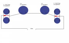
just to close the loop heres the final. wiring it today
Yes, that should work. And it would be a good idea to measure the voltages across each heater, just to make sure the voltage is dividing out as it should.
Chris
- Status
- This old topic is closed. If you want to reopen this topic, contact a moderator using the "Report Post" button.
- Home
- Amplifiers
- Tubes / Valves
- OTL Heater Questions