not really my opinion, but a lot others here have said before, not enough open loop gain is detrimental to stability..
"too much feedback" is not the same as high open loop gains, please look again,
open loop gains is the voltage gain prior to application of negative feedback, and you are correct, too much feedback can cause instability, but that is not what i was saying...
"too much feedback" is not the same as high open loop gains, please look again,
open loop gains is the voltage gain prior to application of negative feedback, and you are correct, too much feedback can cause instability, but that is not what i was saying...
Last edited:
You can reduce 3 stage amp to just 2 stage (just EF86) as I posted before. The OL is only 50. It's stable, distortion is higher that is all. If I use 6F12p, I can increase the OL to about 400, then I reduce the gain by NFB to 50 (400/8). This is also not a problem.
Remember that the OL of Tim OTL must also include the gain of EF86 ( LTP gain 50) before NFB as there is 100% NFB applied to this stage. So there is enough OL gain for 2V sensitivity? I think damping factor can not be overlooked that why I advice OP to try feedback amount by listening to the bass, over /under damped that may matter to you.
Remember that the OL of Tim OTL must also include the gain of EF86 ( LTP gain 50) before NFB as there is 100% NFB applied to this stage. So there is enough OL gain for 2V sensitivity? I think damping factor can not be overlooked that why I advice OP to try feedback amount by listening to the bass, over /under damped that may matter to you.
Last edited:

You can reduce 3 stage amp to just 2 stage (just EF86) as I posted before. The OL is only 50. It's stable, distortion is higher that is all. If I use 6F12p, I can increase the OL to about 400, then I reduce the gain by NFB to 50 (400/8). This is also not a problem.
Remember that the OL of Tim OTL must also include the gain of EF86 ( LTP gain 50) before NFB as there is 100% NFB applied to this stage. So there is enough OL gain for 2V sensitivity? I think damping factor can not be overlooked that why I advice OP to try feedback amount by listening to the bass, over /under damped that may matter to you.
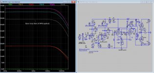
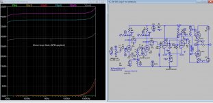
open loop pf the Tim OTL is the gain of the 12ax7 in db, + the gain of the EF86 in db, this is before the application of feedback..
No, really must include output stage gain of about 0.23, because the gain of output stage varied depend of how much bias level is and number of tubes used, the more tube the higher is the gain, how CAN you omit it?
I figure the differece between OL and CL is more than 27 db, or a feedback is 27db (compare to 10 db for other amp)
OL-CL=56-29 db=27 db original (17 dbs more than others)
With 20k (and 470k fb res)
OL-CL= 34-25=9 dbs mods (closer to normal 10 db).
But Futterman OTL3 for example has 30 dbs nfb, it does not use LTP, instead use a high gain 6au8 single stage, a concertina PS, that is the differences how much NFB one circuit it can take. The bottle neck in Tim's amp is in the front end LTP stage and low bandwidth tube used.
Last edited:
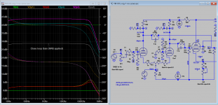
https://www.diyaudio.com/community/threads/questions-about-tim-mellow-6c33c-otl.257100/post-5327639An attempt to fix the spike, here is my attempt with snapper 7k5 and 300p from grid to ground, flatten the peak due to the excessive phase shift of the feedback.
Attachments
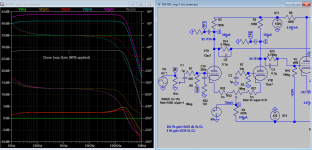
Way back, soon after I had built my Tim Mellow OTL, I discovered when playing around driving it with a square wave into a dummy resistive load that there was a distinct ringing on the leading and trailing edges. I eliminated this by putting a very small capacitor in parallel with the 1Mohm feedback resistor R3. I mean really small; just what is known as a "gimmick" capacitor in some radio circles, made by twisting a couple of short lengths of insulated wire together. Probably no more than 1 or 2pF at the most. I can imagine this might be enough to tame the high-frequency peak you are seeing in your simulation. It would be interesting to know what happens in your sim if you try that instead.https://www.diyaudio.com/community/threads/questions-about-tim-mellow-6c33c-otl.257100/post-5327639An attempt to fix the spike, here is my attempt with snapper 7k5 and 300p from grid to ground, flatten the peak due to the excessive phase shift of the feedback.
I wonder if anyone has any comments on the following. When I constructed my Tim Mellow OTL I found that the plus and minus HT supplies were markedly unbalanced, with HT+ settling to about +185V relative to ground, and HT- settling to about -135V relative to ground. In the end I "solved" the problem by reducing the 1K resistor R33 (from the power transformer centre-tap to ground) to about 75 ohms. Of course, if one shorts out R33 completely then the HT+ and HT- voltages become exactly balanced with respect to ground. But, reducing or eliminating R33 comes at the price of reducing or eliminating the current-limiting safety feature inherent in Tim Mellow's original design.
The reason for the imbalance, of course, is the asymmetry in the power-supply design, with the voltage tripler for the -430V supply being run off just one arm of the otherwise-balanced supply. (I verified, with the tubes removed, that the imbalance went away if I disconnected the capacitor C19 that drives into the tripler.) I suppose one way to solve the problem would be to introduce a complementary +430V tripler using the other arm of the supply, whose sole purpose would be to drive a suitably-chosen dummy load that would then restore the balance. This seems a bit inelegant, to say the least! Another option would be to use a separate small power transformer for the -430V supply. Is there any other way to solve the problem more elegantly, I wonder?
The reason for the imbalance, of course, is the asymmetry in the power-supply design, with the voltage tripler for the -430V supply being run off just one arm of the otherwise-balanced supply. (I verified, with the tubes removed, that the imbalance went away if I disconnected the capacitor C19 that drives into the tripler.) I suppose one way to solve the problem would be to introduce a complementary +430V tripler using the other arm of the supply, whose sole purpose would be to drive a suitably-chosen dummy load that would then restore the balance. This seems a bit inelegant, to say the least! Another option would be to use a separate small power transformer for the -430V supply. Is there any other way to solve the problem more elegantly, I wonder?
0.5p is enough, it's way too small, smaller than the stray capacitance of the wiring and too sensitives.Way back, soon after I had built my Tim Mellow OTL, I discovered when playing around driving it with a square wave into a dummy resistive load that there was a distinct ringing on the leading and trailing edges. I eliminated this by putting a very small capacitor in parallel with the 1Mohm feedback resistor R3. I mean really small; just what is known as a "gimmick" capacitor in some radio circles, made by twisting a couple of short lengths of insulated wire together. Probably no more than 1 or 2pF at the most. I can imagine this might be enough to tame the high-frequency peak you are seeing in your simulation. It would be interesting to know what happens in your sim if you try that instead.
Attachments
Are you sure that is the sole cause ( asymmetry in the power-supply design)? R13 100k, connected to the output is drawing some >2.5mA from HT+(via V2) as well, that is another source of imbalance I think. How about restoring balance by inserting zener/diode into arams of the bridge that is higher?I wonder if anyone has any comments on the following. When I constructed my Tim Mellow OTL I found that the plus and minus HT supplies were markedly unbalanced, with HT+ settling to about +185V relative to ground, and HT- settling to about -135V relative to ground. In the end I "solved" the problem by reducing the 1K resistor R33 (from the power transformer centre-tap to ground) to about 75 ohms. Of course, if one shorts out R33 completely then the HT+ and HT- voltages become exactly balanced with respect to ground. But, reducing or eliminating R33 comes at the price of reducing or eliminating the current-limiting safety feature inherent in Tim Mellow's original design.
The reason for the imbalance, of course, is the asymmetry in the power-supply design, with the voltage tripler for the -430V supply being run off just one arm of the otherwise-balanced supply. (I verified, with the tubes removed, that the imbalance went away if I disconnected the capacitor C19 that drives into the tripler.) I suppose one way to solve the problem would be to introduce a complementary +430V tripler using the other arm of the supply, whose sole purpose would be to drive a suitably-chosen dummy load that would then restore the balance. This seems a bit inelegant, to say the least! Another option would be to use a separate small power transformer for the -430V supply. Is there any other way to solve the problem more elegantly, I wonder?
Last edited:
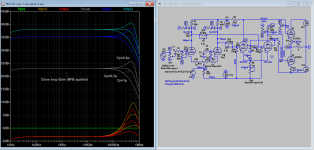
That's nice to see. I just checked an estimate of the capacitance of my twisted-pair capacitor, and indeed it is more like 0.5pF. So the square-wave ringing I was seeing, and the high-frequency peak you found, are very likely related, I suppose.0.5p is enough, it's way too small, smaller than the stray capacitance of the wiring and too sensitives.
It's not a bad way of dealing with the high-frequency peak, I think. That feedback pathway, from the speaker output to the grid of the input tube, is probably the only one that is so sensitive to stray capacitance. I found that the tuning-out of the ringing on the square wave was very easily achieved by adjusting the twisted-pair of wires. And it is then very stable.
https://www.diyaudio.com/community/threads/questions-about-tim-mellow-6c33c-otl.257100/post-6820272Here is the actual freq. response plot, you can clearly see what happened after about 20k.
Last edited:
Well, it is true there are other sources of asymmetry indeed. For example, the HT1 +145V to the V1 driver tube. These are not enough to counterbalance the larger effect from the voltage tripler, though. I guess the answer may be just to put an additional load resistor from the main HT+ to ground, tuned to achieve a balance. I'll play around with this when I get it back on the workbench.Are you sure that is the sole cause ( asymmetry in the power-supply design)? R13 100k, connected to the output is drawing some >2.5mA from HT+(via V2) as well, that is another source of imbalance I think. How about restoring balance by inserting zener/diode into arams of the bridge that is higher?
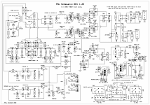
This issue has been address years ago, I remember at least one person has built the remake PSU model, do you think it can solve the problem?
https://www.diyaudio.com/community/threads/new-tim-mellows-otl-project.204960/post-4657979
https://www.diyaudio.com/community/threads/new-tim-mellows-otl-project.204960/post-4657979
In the PSU schematic you are linking to, the centre-tap of the power transformer is connect directly to ground (since your R1 is set equal to 0), and so the possibility of imbalance of the HT+ and HT- supply rails relative to ground does not arise. This is essentially what I was doing in the Tim Mellow amplifier, by either shorting out his 1Kohm resistor R33, or replacing it by a much smaller value. In many ways, this is the simplest and most effective thing to do.This issue has been address years ago, I remember at least one person has built the remake PSU model, do you think it can solve the problem?
https://www.diyaudio.com/community/threads/new-tim-mellows-otl-project.204960/post-4657979
The question really is whether one is concerned about the possibility of speaker damage in the event of a catastrophic tube failure, such as one or other of the output tubes effectively shorting between anode and cathode (or some other failure sending the grid voltage to a level that drives the tube into heavy conduction). If the supply rails are pinned to +150V and -150V by shorting out his R33, then a possible safety protection would be to use a capacitor in series with the loudspeaker. This capacitor needs to be of order 4000uF or so, and furthermore it needs to be bipolar, since one knows not which of the output tubes might fail, so it could find itself having either +150V across it or -150V across it. So one would need two back-to-back electrolytics, each of about 8000uF and at least 150V working voltage, in series. Of course each 4000uF could be achieved with paralleled smaller capacitors.
Another option is to retain the 1Kohm resistor R33 in Tim Mellow's schematic, and try to find a way to achieve an approximate balance of HT+ and HT-. I think now this can be done quite easily simply by adding a padding resistor from HT+ to ground. However, I think there is one point that he has overlooked, concerning what would happen in the event of a catastrophic tube failure. If one of the output tubes were to develop effectively an anode-cathode short (or be driven into heavy conduction by a fault elsewhere), the HT supplies would certainly in principle simply float so that one of the HT rails would go more or less to zero voltage, while the other would go to about +300V or -300V, depending on which arm the fault lay in. But, this means one will only have the protection if the main smoothing capacitors in each arm of the supply are capable of withstanding the 300V across them. In his specific schematic, the capacitors would be driven well above their rated voltage (4 x 63= 252V) if such a fault condition developed. In my case, I am currently using capacitors rated at 200V. This is fine if there is no catastrophic failure, but the capacitors might themselves fail if there were to be a catastrophic tube failure, and then all bets would be off, again, for the speaker.
If I were building mine again, I think I would get capacitors with sufficient working voltage that they could withstand the 300V or so of a catastrophic fault condition.
Alternatively, one can just hope for the best, and put one's faith in fuses.
1k resistor can be used for speaker protection as this PSU does not has the shortcoming you mentioned in the original design. But as you said there are still others problem even you have symmetry by design. I use speaker cut out unit like that of SS amp used to protect speaker in addition to fuse. So I agree there is not much point persuade further. Some people insist on full regulation like Futterman OTL4 to achieve HT balance. I also use separate transformer for each half of PSU, that is one for HT+ and one for HT-, that would minimize imbalance. But since there is DC servos in this amp, if your output tubes are not matched you'll have different current (in R33 1k) that will cause some voltages drop that cause imbalance again, so it should be avoided, unless you don't use DC servos or use completely matched tube (together with symmetry design). If you use load for HT balancing, I think you'll have to adjust again if the tubes are replaced.
Last edited:
Sounds like a good idea. Do you use mosfet switches? I think arcing is a real concern for a mechanical relay that is called upon to interrupt 150V DC, especially with the current being quite high.I use speaker cut out unit like that of SS amp used to protect speaker in addition to fuse.
No, I use 24V DPDT completely sealed relay, with 8A/250v switching capacity. No problems over the years, and I have several amps some are under construction but due problems with questionable brand e-cap in PSU, I need to buy some other brands for trial basis. There is no need to build the cutout unit on board as there some ready make unit can be used instead. My unit will cutout when there is more than _+2V offset, but will resume after 15s or so for minor fault, it wouldn't resume if the fuse is blown happened in a major fault. When first start, it senses the DC voltages from soft start unit, and connect the speaker when the delay timing is reached (< 5mins). Then it's connected to output, convert AC signal to DC for cutout.
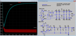
Attached also shows how 1k resistor can protect the speaker as in original design but also with remake sch, but unfortunately the sim will show that it still has some offset in the output (<50mV), not sure it's corrected or not by DC servos.
In the latter sch, I no long used HT 500V, but 320V by grounding it directly instead stacking on top of +170V.
Attachments
Last edited:
- Home
- Amplifiers
- Tubes / Valves
- OTL designed by Tim Mellow with 4 6C33C?