Hey Chris good to see you back. did you get a chance to check on how you tied the center taps on the output tubes to ground? to me it seems the schematic is incorrect that the CT point on the seperate tube heaters were tied that way but maybe I am wrong, would not be a first
Thx again in advance!

I just checked, and I did exactly as shown in the schematic; 6C33C heaters connected in series, and the centre point connected to ground for V4 and to -150V for V5. The two V4 tubes (left channel and right channel) have their series-connected heaters in parallel (i.e. each running from the same 12V winding on T2), and the two V5 tubes (left and right channel) likewise have their series-connected heaters paralleled on the second, separate, 12V winding of T2. I don't think it matters too much how you tie the V4 heaters to ground and the V5 heaters to -150V. I just picked the midpoint of one of the V4's, and tied that to ground, and likewise tied one of the V5 midpoints to -150V. As long as you make sure that the DC voltage between heater and cathode on all tubes is not too big, that is all that really matters.
Chris
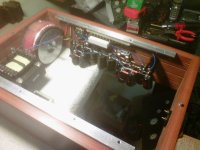
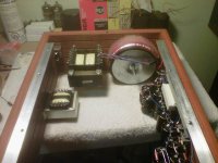
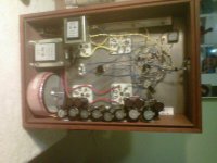
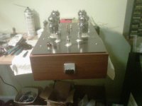
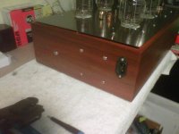
Here we go. Finished her 10 minutes ago. The rear 6C33's are not working currently as I want to get the original amps design functioning first before I move on to that. One other typo in the schematic I found is the HT3 supply in the section where it is shown lifting the heater supply it is not 450 its 430. Enjoy!
Attachments
atmasphere not sure i am understanding u correctly r u saying the V5 tube does not have to be lifted and the V4 does not have to be tied to ground?
Also if you chose to do it as show is it correct? can u tie in directly as soon in the schematic? thx!
Uh, not really sure what you are asking. What do you mean by 'lifted' and how is V4 tied to ground? I don't see *that* in the schematic...
I doubt you would ever find a 6800uf oil-filled cap rated at 175 or 200V! You will have to build up a bank of smaller parts, and that is going to be a lot of parts! That is why electrolytics are popular, and in a case like this, definitely have their place.
Think under``lifted``termin is actualy polarisation of 12,6V~ heater voltage of V5(6c33c) to -150V from (HT4) PSU point to avoid internal Tube heater-kathode breakdown, for same reason 6,3V~ heater voltage is` lifted` to -450V from (HT3) PSU point for V2/V3 EF86 driver tube.
BTW,I dont think is necesary for PSU to use 8 piece of 6800uf/63V- conected in series,its OK to use just two piece of 2200uf/250V- for that purpose,one for + 150V and one - 150V rail(HT2,HT4 point).
Good Luck to All
BTW,I dont think is necesary for PSU to use 8 piece of 6800uf/63V- conected in series,its OK to use just two piece of 2200uf/250V- for that purpose,one for + 150V and one - 150V rail(HT2,HT4 point).
Good Luck to All
Last edited:
yes this is what i was talking about but Chris answered. Also I agree you do not have to use the caps as stated in the article i believe Tims reasoning was due to the cost of a quality cap at a reasonable cost that would reach the value needed. It is very expensive to get a cap of 1600uf to say 2000uf at 250vdc in high quality at a good price.
VERY NICE Des. Your layout is so tiddy, I hope I can do as well. Will you be running it for a whole per the scheem before adding the 2nd pair of tubes? I hope you do so we can get an understanding of how the amp sounds. Great job.
Thx djn
yes I will run it first with the schematic layout and then add the 2 extra tubes over the next few days or a week or so. Actually I am hoping to run it tonight for the first time since i never got a chance yesterday night when i finished it. Had to get the kids to bed, priorities you know. I will keep you posted. I have a pair of NYAL OTL3's and a pair of OTL1's that I use all the time so they have a bit to compete with.
yes this is what i was talking about but Chris answered. Also I agree you do not have to use the caps as stated in the article i believe Tims reasoning was due to the cost of a quality cap at a reasonable cost that would reach the value needed. It is very expensive to get a cap of 1600uf to say 2000uf at 250vdc in high quality at a good price.
'Snap' caps are a good way to solve this dilemma. They are reasonably priced and have good performance. Clamps for mounting them are readily available too.
'Snap' caps are a good way to solve this dilemma. They are reasonably priced and have good performance. Clamps for mounting them are readily available too.
Indeed, I'm using two Cornell-Dubilier 2200mfd 200V snap-in capacitors in parallel for each HT supply, and they seem to be fine. (About $12 each from Mouser.)
Since they do really form part of the audio circuit I have wondered whether I should experiment with adding some smaller "higher quality" capacitors in parallel, but I'm not aware of any shortcoming of the present arrangement that might be improved by this. As a general question, what would be the most likely deficiencies, from an audio viewpoint, in run-of-the-mill electrolytics? Frequency-dependent impedance losses??? If any such degradation occurred at the higher end of the frequency spectrum, then that could be relatively easily fixed by paralleling additional higher-quality capacitors.
As a matter of interest, I did measure the "dynamical" output impedance of the amplifier, and got a figure of about 0.3 ohms, but I only measured at one frequency (1KHz, if I remember correctly). Maybe I should make more extensive measurements over the frequency spectrum.
Chris
Indeed, I'm using two Cornell-Dubilier 2200mfd 200V snap-in capacitors in parallel for each HT supply, and they seem to be fine. (About $12 each from Mouser.)
Chris
Chris are you saying you use one 2200uF to replace C8-C11 and the other to replace C12-C15? Four series 6800uF caps = 1700uF, I guess 2200uF is close enough. My only concern with the increased capacitance is if it affected the H1-H4 votage, if I recall you don't have a problem there.
Brad
Attachments
Chris are you saying you use one 2200uF to replace C8-C11 and the other to replace C12-C15? Four series 6800uF caps = 1700uF, I guess 2200uF is close enough. My only concern with the increased capacitance is if it affected the H1-H4 votage, if I recall you don't have a problem there.
Brad
Actually I decided to go for a bit more smoothing, and I'm using two 2200uF capacitors in parallel for each of the supplies. So 4400uF per supply. I don't think it affects the voltage in any way; it just gives a lower ripple.
Chris
Thanks guys.
Desperateaudio, how's it going?
Brad
Well here's the update:
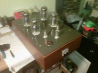
Spent last 2 evenings checking voltages and dialing in the voltages. Tonight i played her for an hour and a few things are worth mentioning. The amp gets real hot but I do not think that surprises anyone. I will be adding DC to the input tube heaters as they will sound better since they are a little loud. Certainly the amp needs to play for a while. I played it on a completely rebuilt 1960 Audax Triaxial speaker of 98dB in a DIY Tannoy horn cabinet. 25 watts seems plenty for this speaker. I will try it tomorrow night with my Quad 63's side by side against one of my NYAL OTL3's. She held current spot on for the entire hour once she warmed up which took about 5 minutes. Do not be surprised if your voltages are not the same as the article. I built it EXACTLY as designed and my voltages are slightly higher everywhere but no big deal.
In general the amp sound nice. I think over the next few day she will sound much better so I will hold my final opion until then. Once I get them on the quads I will report back again. I will not go to 4 output tubes for a little while until I get this amp to break in but I will re-draw the schematic in the meantime for how I see that happening and post it for comments.
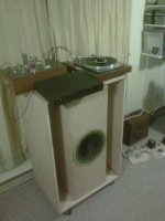
I uploaded a pic of my mono system which is the DIY tannoy and Audax a goldring L72 TT and a kenwood Basic 2 preamp which has a great phono stage.
Thx
Attachments
Last edited:
Hi Chris,
Did you use matched tubes for output? If you did can you advise name of supplier?
Cheers!
No, I didn't match the tubes. I picked up the ones I'm using at the moment on ebay for about $25 each, as far as I recall. (Supplier in Ukraine.) I also have some I bought from thetubestore.com standing by, in case I need to replace the ones I'm using now. I don't think they offer matching on 6C33C tubes. My impression is that until they've been run in for quite a while, any attempt at matching would probably be rather futile. But as far as I have experienced, once the offset and bias has settled down after warming up, everything seems to be reasonably stable.
Chris
- Home
- Amplifiers
- Tubes / Valves
- OTL designed by Tim Mellow with 4 6C33C?