For this schematic can someone provide a parts list that they used please (or one they would use). It's just as a check-list to make sure everything is covered (when I'm costing it up), I don't want to miss anything.
Thanks
"Easy" OTL 40 watts with 6C33C Output Tubes • DIY Audio Projects Forum
Thanks
"Easy" OTL 40 watts with 6C33C Output Tubes • DIY Audio Projects Forum
For this schematic can someone provide a parts list that they used please (or one they would use). It's just as a check-list to make sure everything is covered (when I'm costing it up), I don't want to miss anything.
Thanks
"Easy" OTL 40 watts with 6C33C Output Tubes • DIY Audio Projects Forum
The pdf file of Tim Mellow's article (accessible via a link on the thread you linked to) includes a parts list (you need to double up the amplifier parts (those appearing in Fig. 1) for stereo.
Chris
Is it my imagination, or have the prices on the 6C33C gone up in the last couple of months? I bought a bunch of them for $8 each, now they seem to be higher. I just burned in fourteen 6C33C and twenty-four 6H13C tubes for 72 hours each. Now I just need to make the time to construct the amps. I got sidetracked by a class D amp.  Go figure - from tubes to class D. Who would have guessed I'd like the sound of switching MOSFETs?
Go figure - from tubes to class D. Who would have guessed I'd like the sound of switching MOSFETs? I got sidetracked by a class D amp. Go figure - from tubes to class D. Who would have guessed I'd like the sound of switching MOSFETs?
Welcome to the other side
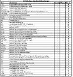
I've knocked up an Excel spreadsheet to help suppliers quote for these parts as a whole, or at least to most of them.
On the schematic (in the Excel file that I can't attach so I've uploaded a pic instead) C10 and C11 have been missed from the drawing, by accident.
I've put the exact same info in the excel file in case you want to use it (PM me) and tailor to suit, this isn't the one I'll send off merely the one in the magazine article itself (included on tab 2).
I've got the quantities right haven't I?
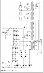
I thought to omit the ammeters but, while you're here, on Fig 2 Power Circuit can Caps C8-C11 and caps C12-C15 be replaced by one cap each (say 6800mF 250V) instead? This also does away with resistors R23-R30 too..?
Thanks
Nathan
PS I'll trawl the other threads again but if there are any things I could do without ordering please nudge me. This is to power full range 96dB 8 Ohm speakers voigt pipe.
PPS If the pics are a little small on your display hold down CTRL and scroll-wheel up once you've clicked to maximise them.
On the schematic (in the Excel file that I can't attach so I've uploaded a pic instead) C10 and C11 have been missed from the drawing, by accident.
I've put the exact same info in the excel file in case you want to use it (PM me) and tailor to suit, this isn't the one I'll send off merely the one in the magazine article itself (included on tab 2).
I've got the quantities right haven't I?
I thought to omit the ammeters but, while you're here, on Fig 2 Power Circuit can Caps C8-C11 and caps C12-C15 be replaced by one cap each (say 6800mF 250V) instead? This also does away with resistors R23-R30 too..?
Thanks
Nathan
PS I'll trawl the other threads again but if there are any things I could do without ordering please nudge me. This is to power full range 96dB 8 Ohm speakers voigt pipe.
PPS If the pics are a little small on your display hold down CTRL and scroll-wheel up once you've clicked to maximise them.
Attachments
TIM MELLOW OTL
Have just finished my second one of these amps, this time using 6C33Cs (first one used 6C41Cs) Sounds very similar, but goes louder! I re-jigged the schematic but can't attach it here as the file is too big. It makes it easier to build from re-drawn. If anyone wants it, please mail me and I'll post it as an attachment.
Regards,
David.
Yes, you can just replace the series-connected power supply capacitors with one (or more in parallel) that can take the full voltage. Indeed, you can omit the ammeters. I just used a low-value resistor (0.1 ohm) across a couple of tip jacks, so that you can measure the voltage (and hence current) with a DVM. It's a good idea to put a resistor across each PS capacitor, so that it discharges after the power is turned off. Might help to avoid a nasty shock!I've knocked up an Excel spreadsheet to help suppliers quote for these parts as a whole, or at least to most of them.
On the schematic (in the Excel file that I can't attach so I've uploaded a pic instead) C10 and C11 have been missed from the drawing, by accident.
I've put the exact same info in the excel file in case you want to use it (PM me) and tailor to suit, this isn't the one I'll send off merely the one in the magazine article itself (included on tab 2).
I've got the quantities right haven't I?
I thought to omit the ammeters but, while you're here, on Fig 2 Power Circuit can Caps C8-C11 and caps C12-C15 be replaced by one cap each (say 6800mF 250V) instead? This also does away with resistors R23-R30 too..?
Thanks
Nathan
PS I'll trawl the other threads again but if there are any things I could do without ordering please nudge me. This is to power full range 96dB 8 Ohm speakers voigt pipe.
PPS If the pics are a little small on your display hold down CTRL and scroll-wheel up once you've clicked to maximise them.
Chris
I've knocked up an Excel spreadsheet to help suppliers quote for these parts as a whole, or at least to most of them.
On the schematic (in the Excel file that I can't attach so I've uploaded a pic instead) C10 and C11 have been missed from the drawing, by accident.
I've put the exact same info in the excel file in case you want to use it (PM me) and tailor to suit, this isn't the one I'll send off merely the one in the magazine article itself (included on tab 2).
I've got the quantities right haven't I?
I thought to omit the ammeters but, while you're here, on Fig 2 Power Circuit can Caps C8-C11 and caps C12-C15 be replaced by one cap each (say 6800mF 250V) instead? This also does away with resistors R23-R30 too..?
Thanks
Nathan
PS I'll trawl the other threads again but if there are any things I could do without ordering please nudge me. This is to power full range 96dB 8 Ohm speakers voigt pipe.
PPS If the pics are a little small on your display hold down CTRL and scroll-wheel up once you've clicked to maximise them.
A couple of other things:
1. Make sure you get phono sockets that are isolated from the chassis, to avoid ground loops.
2. Handles, as in the photo in the Tim Mellow article, are a very good idea!
Chris
does anyone has a stability problem with the amp? after 5 hours one power tube goes red. i put amp off, waited 15 min and it works fine again.
i've heard that there's a frequence peak in output signal and it(feedback?) needs RC circuit to get rid off the peak. i think RCA otl has reactance network to correct this issue...

i don't have spectrum analyser to check frequence sweep and locate peak. 8 ohm load should need 8ohm resistor and capacitor value should be calculate when peak frequence is located....
comments?
i've heard that there's a frequence peak in output signal and it(feedback?) needs RC circuit to get rid off the peak. i think RCA otl has reactance network to correct this issue...
i don't have spectrum analyser to check frequence sweep and locate peak. 8 ohm load should need 8ohm resistor and capacitor value should be calculate when peak frequence is located....
comments?
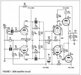
The amp is class A totem pole PP output. But it can still output 70 watts!
I actually did as you advised but I made the resistors 5 ohms. After running multiple simulations I found that 5 ohms will reduce the power out by about 10% and raise the output impedance from 0.12 to 0.15 ohms (approx.) which is no big deal.
I'll actually probably reduce them to 2 ohms (your suggestion) and raise the voltage on the rails to +/-160 (I will have no choice with the trannys I'm using) which should push the output over 70 watts.
I also added C5 and C6 to control the bandwidth of the amp and tone down a slight high frequency resonance above the audio spectrum.
Here's the latest schematic:
An externally hosted image should be here but it was not working when we last tested it.
is this design work perfect ?
You will want a set of ZEROs (Autoformers offered by ZeroImpedance- Improve your speaker sound quality with the use of an autoformer.).
Stuart,
All I can say is that I've used them on both a KT88 PP amp (the "Oddwatt" SIPP amp designed by Bruce Heran)
Sampleaccurate, I have the same KT88 amp and I use it constantly. Did you finish an OTL and, if so, how do they compare?
Thanks
Steve
I am looking to make this my next build after my EL84 build, and I wanted to use an LM1084 for the heaters, one per tube.
I noticed that one of the heater windings on the Tim Mellows design is biased to ground, and the other to -150v.
Will this cause issues? Do I need a negative regulator for the negative biased winding? Or do I need a positive and negative reg on the top and bottom of each winding?
I noticed that one of the heater windings on the Tim Mellows design is biased to ground, and the other to -150v.
Will this cause issues? Do I need a negative regulator for the negative biased winding? Or do I need a positive and negative reg on the top and bottom of each winding?
Last edited:
- Home
- Amplifiers
- Tubes / Valves
- OTL designed by Tim Mellow with 4 6C33C?