Hy Mad_K ,
On th following power supply schematic , there are no values
for tce capacitors C6 & C8 .
http://www.diyaudio.com/forums/atta...tamp=1139436029
I think I can also put 22 000µF , 47 000µF or even more .
@ + Philippe.
On th following power supply schematic , there are no values
for tce capacitors C6 & C8 .
http://www.diyaudio.com/forums/atta...tamp=1139436029
I think I can also put 22 000µF , 47 000µF or even more .
@ + Philippe.
Tyimo said:Hi!
I will try to invitate here Circlotron, Who has already succesfully built an amp with choke loading. Maybe He can help me or us.
Tyimo
/Circlotron - pokes head through doorway.

Hello Tyimo. Just today I saw your S.O.S. invitation
") to come over here and see the excitement. I have not read the whole thread, but enough to get an idea of what is happening. Have you got anything going yet? Choke-loaded source-follower is a great way to make a diy amplifier and once you have played with one for a while you might never go back to the other kind.
to come over here and see the excitement. I have not read the whole thread, but enough to get an idea of what is happening. Have you got anything going yet? Choke-loaded source-follower is a great way to make a diy amplifier and once you have played with one for a while you might never go back to the other kind. First suggestion - don't use too big a mosfet. If you have a standing current of say 2 amps then use a 10 amp mosfet, not a 50 amp one. Mosfets are a bit nonlinear if used at too small a current compared with their maximum. In mine I used a 500 volt 32 amp one because I had a whole tube of them and they are a TO-247max package (no hole) so there is lots of contact area for dissipating 100 watts of heat, but otherwise it was not a very good choice. Still sounds ok even if in theory it could be better.
Second suggestion - use a logic level mosfet because these generally have a higher transconductance than a normal one. Result is the source follows the gate more closely.
-Looking at the transfer curves, a low current logic level mosfet should be much more linear. Looks like they are only available in TO220 packages. I noticed the IRLZ14; 43W, 60V, 10A. Runnig it in a source follwer with about 12VDS @2A should be nice. However, one would have to go for water cooling to get rid of the heat because of the 3,5'C Rjc 
FOUND IT!
I found a very promising part in my suppliers catalog; the RFP12N10L fron Intersil. 60W, 12A, 100V. The transfer curve is totally different from the standard IR parts; much more linear. It has more like a triode character rather than the typical pentode character. Power-wise it looks doable in low power OTA/SEWA style amp up to 25W dissipation. It has 2'C/W RthJC. Adding a aluminium-oxide insulating pad with 0,3'C/W and counting some losses we are up to 2,5'C total Rth Junction to Heatsink. If we manage to keep the heatsink at 40-45'C above ambient we can get a reliable amp (junction temp not much above 100'C) SEWA=>22,5W*2,5=56'C +45'C=101'C
I found a very promising part in my suppliers catalog; the RFP12N10L fron Intersil. 60W, 12A, 100V. The transfer curve is totally different from the standard IR parts; much more linear. It has more like a triode character rather than the typical pentode character. Power-wise it looks doable in low power OTA/SEWA style amp up to 25W dissipation. It has 2'C/W RthJC. Adding a aluminium-oxide insulating pad with 0,3'C/W and counting some losses we are up to 2,5'C total Rth Junction to Heatsink. If we manage to keep the heatsink at 40-45'C above ambient we can get a reliable amp (junction temp not much above 100'C) SEWA=>22,5W*2,5=56'C +45'C=101'C
Re: FOUND IT!

A lot of IR datasheets have one of the graph axes logarithmic instead of linear. Can be misleading.Mad_K said:The transfer curve is totally different from the standard IR parts; much more linear.
The outer legs were originally gapped at ~6mm so I removed the gap material andTyimo said:How did you compress you custom made EI core chokes?
 the core halves toward each other. There must have been some extra gap material between the ends of the centre leg because the two core halves stopped at about 1mm spacing. I was just lucky.
Looks good Tyimo
-Do you have a pot in the bias network?
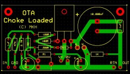
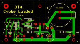
-The impedance seen from your source is the paralelled value of the input bleeder resistor to gnd and the gate bias resistor. If you want 200K Zin, you must use 1M bleeder and 250K gate resistors. How about mounting holes on the lower side of the pcb?
-Do you have a pot in the bias network?
-The impedance seen from your source is the paralelled value of the input bleeder resistor to gnd and the gate bias resistor. If you want 200K Zin, you must use 1M bleeder and 250K gate resistors. How about mounting holes on the lower side of the pcb?
Re: Re: FOUND IT!
 Doh! Now I noticed! It still looks like RFP12N10L (Its) is a good one to try
Circlotron said:
A lot of IR datasheets have one of the graph axes logarithmic instead of linear. Can be misleading.
Doh! Now I noticed! It still looks like RFP12N10L (Its) is a good one to try Hi Mads!
Thanks for the suggestions!
You wrote one time to me : "Input impedance is essentially the resistor from the voltage divider to the gate (100K)." ?!?
As you wish my Master!
I have the trimmer pot in series with R2 (in the voltage divider, down to ground) to get the adjustable value for different bias voltage. Isn't it enough?
Greets:
Tyimo
Thanks for the suggestions!
The impedance seen from your source is the paralelled value of the input bleeder resistor to gnd and the gate bias resistor. If you want 200K Zin, you must use 1M bleeder and 250K gate resistors.
You wrote one time to me : "Input impedance is essentially the resistor from the voltage divider to the gate (100K)." ?!?
How about mounting holes on the lower side of the pcb?
As you wish my Master!
Do you have a pot in the bias network?
I have the trimmer pot in series with R2 (in the voltage divider, down to ground) to get the adjustable value for different bias voltage. Isn't it enough?
Greets:
Tyimo
Attachments
- Status
- This old topic is closed. If you want to reopen this topic, contact a moderator using the "Report Post" button.
- Home
- Amplifiers
- Pass Labs
- OTA - One Transistor Amplifier