anatech said:Hi Gene,
It's a long shot, but try and tack in another one of your transformers. Don't cut the leads yet.
-Chris
Way ahead of you, I just tryd 2 more, I left the leads full, Gave me a chance to move them around to see if location had an effect.
"Guess what"
.
.
.
.
.
.
.
.
.
.
.
.
.
.
.
.
.
.
No Change!

Was clearly worth a go though, Kind of clears up potential location or orientation issues that might have contributed.
I tryd both versions of the transformers, They sell one that is on 2" center, and 1 that has A UL tap and 2 3/8 inch mounting hole centers.
Welp, Seeing as I have just about replaced everything, One last ditch effort, I'll replace the volume and treble pots. The bass pot has no direct effect on the symptom as far as I can Tell. In fact, It actually does very little on either amp.
Gene,
Stop replacing parts. That is not the issue. See my post.
http://www.diyaudio.com/forums/showthread.php?postid=763787#post763787
Stop replacing parts. That is not the issue. See my post.
http://www.diyaudio.com/forums/showthread.php?postid=763787#post763787
Re: where are your grounds??
Actually joel,
The grounds are a bit difficult to read seeing as I had only limited colors of wire.
The Tube socket is basically being used as a poor mans star ground, A practice thats been in use for many decades. I highlited the path in pink to clarify to actual points.
I was trying to avoid using the chassis contact points for grounding. ( Paint is removed from all metal to metal contact points)
The ONLY grounds that are not bused via the socket or cap lugs are the shielded leads I added this morning, They are attached to a chassis lug next to the 12AX7, The other is at the output jack, It is attached well to the chassis. I junpered those points to ground with no change.
See Picture
Pink Highlights
gene
Joel said:Gene,
Look closely at your inside layout picture again. I see five or six seperate "ground" points, which are merely the lugs on the tube sockets, and/or capacitor cans. They don't even seem to be tied to the chassis in some cases. You're assuming these are all good COMMON grounds for the signal. I wouldn't assume that at all. Especially not on a painted chassis like that Hammond box.
All your circuit "grounds" should be attached to a single heavy bus wire of at least 16ga, and then attached to the chassis at a single point (usually one of the power transformer bolts). That point should be scraped down to bare metal on a painted chassis.
Joel
Actually joel,
The grounds are a bit difficult to read seeing as I had only limited colors of wire.
The Tube socket is basically being used as a poor mans star ground, A practice thats been in use for many decades. I highlited the path in pink to clarify to actual points.
I was trying to avoid using the chassis contact points for grounding. ( Paint is removed from all metal to metal contact points)
The ONLY grounds that are not bused via the socket or cap lugs are the shielded leads I added this morning, They are attached to a chassis lug next to the 12AX7, The other is at the output jack, It is attached well to the chassis. I junpered those points to ground with no change.
See Picture
Pink Highlights
gene
Heres a Picture of the unit that seems to work perfrectly for ref.
Basically this one should have been more vunerable than the new one as I ignored keeping minumal lead lengths in some places.
Working unit
Basically this one should have been more vunerable than the new one as I ignored keeping minumal lead lengths in some places.
Working unit
"The Tube socket is basically being used as a poor mans star ground."
A "star ground" is all the circuit ground connections made individually to a single point on the chassis. Not multiple tie points each connected to the chassis.
What you have happening in your amplifier is positive feedback. There is a path occuring you're not aware of, or something is not "grounded" that you think is. Also, when you use mutliple chassis grounds, there can actually be a difference of potential between them, and induced AC voltages.
I know using the chassis as a ground plane, and the tube sockets as ground points has been done before (especially in guitar amps), but it was never good practice, and shouldn't be used.
Joel
Ok, I understand what your saying Kind of,
Looking close, There are a total of 5 points in which ground actually contacts the chassis.
The Can Cap mounting is isolated from the chassis, Rules that one out? It connects to earth only via the highlited blue & white wire from the transformer CT's and or the lead between the socket and cap lug.
#1 The Tube socket lugs(virtually a terminal strip)
#2 The Lug at the 12AX7( Added Today with no effect)
#3 The Lug where the bypass caps are attached
#4 The input jack
#5 The output jack
#1 is hard wired to socket lug
#3 is hard wired to socket lug
#4 is hard wired to socket lug
So, I guess in my eyes the only points in which the chassis is "relied" upon as ground is the output jack & the solder lug where the shielding of the signal leads connect. I added that this morning mounting the 68K resistor directly on socket pin 2.
I Jumpered the ground side of output jack directly to earth with no change.
I jumpered the earth to the solder lug, no change.
Question, Earthing,
On Amp #1 (working) I have earth directly conected to the chassis, Then Directly to the cap lug. A seperate wire then returns to the transformer CT's.
Could the Cap and its proximity to the PT be my source?
Thats a pretty big piece of metal floating up there and its lugs are ties for several componets.
gene
I suggest that you pull the output tube and probe the preamp output with a scope or the input of another amplifier to see if it still oscillates. This will tell you if it's local to the preamp front end or from the output back to the input.
Guessing here, the 15K resistor to ground off the tone stack should be grounded close to the front end, say to the same point as the first tube. Grounded close to the output stage or where current flows from the output stage can form a feedback path where the tone stack senses ground shift from the output stage.
By the way, I only see heater and output transformer wires on pin 8 of the 5Y3, there is a wire to the cap - I hope?
Pete B.
By the way, I only see heater and output transformer wires on pin 8 of the 5Y3, there is a wire to the cap - I hope?
Its there, Follow the twisted pair back to the transformer, At the topright lug on the PT in photo is a wire that connects directly to the cap.
Its really odd to me why these 2 amps work so differently. Both are so close to the same, Yet I can not for the life of me get the working amp to expose a similar issue.
It hits a cerain point and its like flipping a switch.
But hey, I have tryd 90% of the suggestions thus far, I am not giving up yet.
Looking at the original schematic, ( Dont kick me yet )
The PT has no center tap on the 6.3V wind. It shows one side as grounded.
Should I also try that approach?
Gene
"So, I guess in my eyes the only points in which the chassis is "relied" upon as ground is the output jack & the solder lug where the shielding of the signal leads connect."
Hi Gene,
We seem to not be communicating for some reason. You should realize that all of the tube socket tie points you listed are also "relying on the chassis". You can argue with me if you like, or you can simply realize that the construction method you chose is problematic at best.
Hi Gene,
We seem to not be communicating for some reason. You should realize that all of the tube socket tie points you listed are also "relying on the chassis". You can argue with me if you like, or you can simply realize that the construction method you chose is problematic at best.
Hi Gene:
Just a dumb guess, but here is another experiment. Try unbolting the input and output jacks from the chassis. Arrange them so that they are not touching the chassis, and try again. There could be a feedback path through the chassis. If you rember all of the old Marshalls used plastic isolated jacks.
Good Luck
Joel said:"So, I guess in my eyes the only points in which the chassis is "relied" upon as ground is the output jack & the solder lug where the shielding of the signal leads connect."
Hi Gene,
We seem to not be communicating for some reason. You should realize that all of the tube socket tie points you listed are also "relying on the chassis". You can argue with me if you like, or you can simply realize that the construction method you chose is problematic at best.
Joel,
I agree that there is clearly an interaction taking place, But, If I floated the tube socket above the chassis, It is still connected to ground via a hard wire, as Is the Cap.
So, I concidered the socket lugs as nothing more than a terminal strip surrounding the socket.
Now, I guess the real trick is locating the points causing the interacting end results.
Hi Gene,
Did you try swapping all the tubes from the known working unit?
It's important to remember that these tubes amplify at RF frequencies so like it or not you have an RF circuit and therefore layout is very important. The simple answer once you've ruled out everything else is to duplicate the layout of the working unit. I'd do the output tube cathode resistor first, then continue from the front end. You might want to verify with an ohm meter that every resistor is the correct value, just in case before you start.
Pete B.
OK Guys,
Here's where I am.
I stayed up till 4:25AM last night rebuilding the entire unit.
For Joel, I followed his advice as best as possible by making a Bus type ground, " A Single attachment point to the chassis".
I also took Tubelabs advice and installed the Marshall like plastic isolated input and output jacks.
Did it before I re-wired the unit, And also all along the way after each change. Plus Several New sets.
I know that as well as all the other great pieces of advice are very valid and I do greatly appreciate each and every one!
There are no componets attached in any way to the previous solder tabs on the sockets, nor the can cap.
The Bus ground is attached to the chassis on the mounting bolt of the PT. The earth from the IEC jack is also connected at exactly the same location.
EVERY resistor and bypass cap has been replaced , All were checked prior to instalation.All wires associated wires related to my previous grounding plan have been replaced.
So, The only parts left are the Electrolytic Can Cap, The three pots, The signal caps which I have already replaced, And the transformers.
Picture1
Picture2
End Result?
SAME Problem !
@ 50% volume with no guitar plugged in it screams terribly.
@ 100% treble and 90% volume, It Cuts of.
@ 100% Volume and 90% treble it Cuts off
All things being equal so far, And since I have done this much additional work, I am going to replace the pots which seem to test fine while disconnected, JUST to rule out the remote possibility.
Another hunch might be a section of the can cap failing? That would certainly ruin the limited de-coupling of the preamp which could cause a severe oscillation?

OK who is taking bets?? haha
Gene
Here's where I am.
I stayed up till 4:25AM last night rebuilding the entire unit.
For Joel, I followed his advice as best as possible by making a Bus type ground, " A Single attachment point to the chassis".
I also took Tubelabs advice and installed the Marshall like plastic isolated input and output jacks.
Did you try swapping all the tubes from the known working unit?
Did it before I re-wired the unit, And also all along the way after each change. Plus Several New sets.
I know that as well as all the other great pieces of advice are very valid and I do greatly appreciate each and every one!
There are no componets attached in any way to the previous solder tabs on the sockets, nor the can cap.
The Bus ground is attached to the chassis on the mounting bolt of the PT. The earth from the IEC jack is also connected at exactly the same location.
EVERY resistor and bypass cap has been replaced , All were checked prior to instalation.All wires associated wires related to my previous grounding plan have been replaced.
So, The only parts left are the Electrolytic Can Cap, The three pots, The signal caps which I have already replaced, And the transformers.
Picture1
Picture2
End Result?
SAME Problem !
@ 50% volume with no guitar plugged in it screams terribly.
@ 100% treble and 90% volume, It Cuts of.
@ 100% Volume and 90% treble it Cuts off
All things being equal so far, And since I have done this much additional work, I am going to replace the pots which seem to test fine while disconnected, JUST to rule out the remote possibility.
Another hunch might be a section of the can cap failing? That would certainly ruin the limited de-coupling of the preamp which could cause a severe oscillation?
OK who is taking bets?? haha
Gene
Hi Gene,
You certainly have been through the ringer on this. I feel for you.
Bypass each section of the filter cap with, say 10uF or so. Man, I can't imagine what it would be if it isn't this!
I wish you luck and sleep. Congrats! You are a member of the oscillator club!
Best regards,
-Chris
You certainly have been through the ringer on this. I feel for you.
Bypass each section of the filter cap with, say 10uF or so. Man, I can't imagine what it would be if it isn't this!
I wish you luck and sleep. Congrats! You are a member of the oscillator club!
Best regards,
-Chris
anatech said:Hi Gene,
You certainly have been through the ringer on this. I feel for you.
Bypass each section of the filter cap with, say 10uF or so. Man, I can't imagine what it would be if it isn't this!
I wish you luck and sleep. Congrats! You are a member of the oscillator club!
Best regards,
-Chris
Cheerleaders in my sleep woke me already chanting.
2
4
6
8
We Know How To
Oscillate!
Hi Gene,
I know the feeling of being determined to find the problem and have had my share of late nights.
Have you tried the grid stopper on the second stage? Fender leaves these things out, and it's fine if the layout is such that there is no oscillation, but it's important to make the design more tolerant of layout differences. It will not alter the sound.
I don't know what type of cathode bypass cap Fender used around the time of the early Champs but I've read that Sprague tantalums were used in the 1960s. Those aluminum electrolytics probably self resonate just above the audio spectrum. Still, I think that the problem is grounding, and the grid stopper would be my first choice.
By the way, if I read correctly your OT is center tapped for push pull, do you know the turns ratio for the Fender, and if using half or the full wind is closer for this transformer? It's something to think about.
Note that when you turn both the volume and treble all the way up there is no resistance between the first stage plate and the second stage grid, just the 250 pF cap. Turning one control down is similar to having the control act as a grid stopper.
Pete B.
By the way, if I read correctly your OT is center tapped for push pull, do you know the turns ratio for the Fender, and if using half or the full wind is closer for this transformer? It's something to think about.
Nope, Its single ended with a UL Tap.
TF103-48
A new single-ended output transformer with a 5000 ohm primary and both 4 and 8 ohm secondary connections.
Brand new production, and made right here in Chicago, USA.
A bolt-on replacement for Fender Champs, but also useful for many do-it-yourself projects and repairs on vintage amplfiers & radios. Typically used with tubes such as 6BQ5/EL84, 6BM8/ECL82, 6AQ5/EL90, 6CM6, 6V6-GT.
This latest version now includes a screen tap for optional pseudo-triode "ultralinear" operation. If you don't need it, just tape up the extra wire.
Shipping weight 1 lb.
Transformer is rated 100 Hz to 20 KHz -2 dB at 5 watts with 40 ma (maximum recommended) primary current. Reducing primary current improves the bandwidth ,because this is a single ended transformer.
I don't know what type of cathode bypass cap Fender used around the time of the early Champs but I've read that Sprague tantalums were used in the 1960s. Those aluminum electrolytics probably self resonate just above the audio spectrum. Still, I think that the problem is grounding, and the grid stopper would be my first choice.
Grounding? The grounding of what?
Now that the pots are swapped out, I have 2 items, The Can Cap, and PT. My moneys on the cap but I wont be back on it till late saturday.
Gene
@ Trout
This may be a little late since you've re-done the offending amp, but I'll post it anyway.
Ok, after looking at your fotos there are some grounding issues!
1. The Mains gnd should be attached to the chassis at the earliest moment, near the power cord recepticle; NEVER directly to the PS or signal gnds at any time!
2. A redundent gnd wire from tube socket to lug strip, which is attached to the chassis at both ends.
3. You have gnds all over the place that are at multiple points on the chassis.
4. The is no such thing as GROUND!
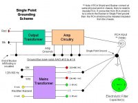
The easiest way to impliment grounding in your case would be a single point bus grounding scheme. One of the most desierable chassis grounding points would be at the metal can PS cap with a grounding bus returning there. Some amps have the grounding bus attached to the chassis at/near the input jack. You may need to use a few more lug strips to accomplish this, but it's the way to go.
Now that's said, I would suggest putting a 4.7k 1/2 watt grid stopper at the output tube's grid, even if it doesn't stop the oscillation because it's always a good idea at that position.
I have a block diagram that I downloaded from somewhere showing a single point grounding scheme. I hope it will be OK to post it here as I think it will help you greatly.
Cheers
Wayne
"My God! They're using TOOLS!" Dr. Herbert West, a.k.a. Jeffery Combs - "Bride Of Re-Animator"
This may be a little late since you've re-done the offending amp, but I'll post it anyway.
Ok, after looking at your fotos there are some grounding issues!
1. The Mains gnd should be attached to the chassis at the earliest moment, near the power cord recepticle; NEVER directly to the PS or signal gnds at any time!
2. A redundent gnd wire from tube socket to lug strip, which is attached to the chassis at both ends.
3. You have gnds all over the place that are at multiple points on the chassis.
4. The is no such thing as GROUND!
The easiest way to impliment grounding in your case would be a single point bus grounding scheme. One of the most desierable chassis grounding points would be at the metal can PS cap with a grounding bus returning there. Some amps have the grounding bus attached to the chassis at/near the input jack. You may need to use a few more lug strips to accomplish this, but it's the way to go.
Now that's said, I would suggest putting a 4.7k 1/2 watt grid stopper at the output tube's grid, even if it doesn't stop the oscillation because it's always a good idea at that position.
I have a block diagram that I downloaded from somewhere showing a single point grounding scheme. I hope it will be OK to post it here as I think it will help you greatly.
Cheers
Wayne
"My God! They're using TOOLS!" Dr. Herbert West, a.k.a. Jeffery Combs - "Bride Of Re-Animator"
Attachments
Trout said:
Grounding? The grounding of what?
Now that the pots are swapped out, I have 2 items, The Can Cap, and PT. My moneys on the cap but I wont be back on it till late saturday.
Gene
Grounding would take some time to discuss in detail, I actually think your chassis based version should have worked fine and was more in line with the vintage concept. I can get into the details later - you have to think of every length of wire as inductance, and think in terms of current loops to get some insight into what's going on with the ground system. First, please try the grid stopper on the second stage, remember that the tube Rin is probably well over 10 Meg so it will not alter the tone or gain, it simply isolates the stray capacitances inside the tube from the wiring inductance around it.
Here's the Fender layout, perhaps it will give you some ideas:
http://www.ampwares.com/ffg/schem/champ_aa764_layout.gif
Note that long wires in the layout are inductors at RF and they can form resonant circuits with other capacitances, that either slow down the circuit and might help stability, or resonate and hurt stability - it is complicated.
Pete B.
- Status
- This old topic is closed. If you want to reopen this topic, contact a moderator using the "Report Post" button.
- Home
- Amplifiers
- Tubes / Valves
- Oscillation Mystery