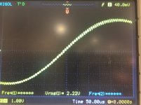
Hi, thanks for your reply, i added those resistors to grid of the first tube and the noise gone, now there is two problem, a steady hum, that i assume is because of the filament supply, it doesn't get any louder when volume turns up, and the second problem is that the frequency response in not flat, its high from 20 to 500 hz, then go's down to 1.3 khz and then rise up to 3khz and stays as the same when is 50 hz.
SE KT88 111.1Khz oscillation
Im reaching out for suggestions as to why i might be getting this 111.1 khz oscillation on both channels of an amplifier Ive built.
Ive tried all sorts of work arounds and experiments on one channel to try to pinpoint where this is originating. One of the last things I have just tried today is Cathode biasing the KT88’s rather than fixed bias and this has killed the oscillation.
The other way is by shunting from P1 terminal ( on OPT) to ground. this also kills the oscillation. Im really hoping to understand why this is occurring in the first place to avoid it rather than introducing more components to fix it.
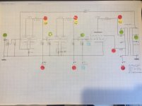
Can provide more info but have attached a schematic of the amplifier stages with some measurements (although measurements may not be clear)
Cheers
Harry
Im reaching out for suggestions as to why i might be getting this 111.1 khz oscillation on both channels of an amplifier Ive built.
Ive tried all sorts of work arounds and experiments on one channel to try to pinpoint where this is originating. One of the last things I have just tried today is Cathode biasing the KT88’s rather than fixed bias and this has killed the oscillation.
The other way is by shunting from P1 terminal ( on OPT) to ground. this also kills the oscillation. Im really hoping to understand why this is occurring in the first place to avoid it rather than introducing more components to fix it.
Can provide more info but have attached a schematic of the amplifier stages with some measurements (although measurements may not be clear)
Cheers
Harry
Attachments
Connecting the OPT P1 to ground shorts out B+ to ground. Using a capacitor connected to ground shorts AC to ground. Of course the oscillation stops.
You have a 3 stage amplifier, and global negative feedback.
But there is no apparent dominant high frequency rolloff pole.
And there is no compensation cap across the feedback resistor the one that connects from the 16 Ohm tap to the input tube cathode.
What is the dominant pole?
The output transformer; the Miller effect capacitance of one of the tubes?
You are paralleling triodes, tying the cathodes together, the plates together, and the grids together. Where are any of your individual grid stopper resistors on each grid (connected directly to the grid pins of the tube sockets.
The input tube, 12AT7 is an RF tube (think RF oscillator, unless it is dealt with properly).
I can not read the schematic to see what the second dual triode tube type is.
You changed from fixed bias to self bias. Did you bypass the self bias resistor with a bypass cap?
It also may be your grounding techniques. You may have a ground loop (like the currents of a later stage that is causing a small signal to an earlier stage's ground point.
One time when I paralleled the cathodes, plates, and grids of a 12AY7, I had to use individual 1k grid stopper resistors, And also had to use 1k individual plate resistors, and joined the other end of those 1 k resistors to the plate load resistor (the plates were separated by 1k + 1k = 2k).
Design and build an amplifier and get an oscillator.
Design and build an oscillator and get an amplifier.
It happens more often than you think.
If you can, please turn up the contrast on your scanner, printer, camera.
Then attach a more legible copy of the schematic.
Last edited:
You need to reduce the open loop bandwidth to form a dominant pole. Try a series RC network
from the first plate to ground, something like 5.1k in series with 180pF/400V. Make the capacitor
a little larger if necessary.
Thanks for your suggestion rayma, when you said first plate, Are you suggesting a 5.1k in series with a low value cap from the P1 terminal to ground from the OPT? or first plate meaning first stage plate (12AT7) Thanks!
Connecting the OPT P1 to ground shorts out B+ to ground. Using a capacitor connected to ground shorts AC to ground. Of course the oscillation stops.
You have a 3 stage amplifier, and global negative feedback.
But there is no apparent dominant high frequency rolloff pole.
And there is no compensation cap across the feedback resistor the one that connects from the 16 Ohm tap to the input tube cathode.
What is the dominant pole?
The output transformer; the Miller effect capacitance of one of the tubes?
You are paralleling triodes, tying the cathodes together, the plates together, and the grids together. Where are any of your individual grid stopper resistors on each grid (connected directly to the grid pins of the tube sockets.
The input tube, 12AT7 is an RF tube (think RF oscillator, unless it is dealt with properly).
I can not read the schematic to see what the second dual triode tube type is.
You changed from fixed bias to self bias. Did you bypass the self bias resistor with a bypass cap?
It also may be your grounding techniques. You may have a ground loop (like the currents of a later stage that is causing a small signal to an earlier stage's ground point.
One time when I paralleled the cathodes, plates, and grids of a 12AY7, I had to use individual 1k grid stopper resistors, And also had to use 1k individual plate resistors, and joined the other end of those 1 k resistors to the plate load resistor (the plates were separated by 1k + 1k = 2k).
Design and build an amplifier and get an oscillator.
Design and build an oscillator and get an amplifier.
It happens more often than you think.
If you can, please turn up the contrast on your scanner, printer, camera.
Then attach a more legible copy of the schematic.
Thanks for your input!
Actually I have not bypassed the cathode bias resistor with a cap yet as it still has not arrived in the mail but that is the intention (I was told by someone else that this is not necessary in SE design however)
Yes I have tried grid stoppers on everything and did not help my problem.
Apologies for the quality of the picture, I dont own a scanner but have access to one next week. The second tube is a 12BH7a
I disconnected the NFB fairly early on in my fault finding and interestingly found that holding the NFB wire (which was still connected to the cathode of the first stage) in close proximity to the SG connection that the oscillations disappeared almost completely. But no answer your question I am not using a compensation capacitor with the NFB resistor. Im not sure of the benefit of this capacitor but would be happy to add something. with The NFB circuit I aim to install a pot to give some control until i decide what works best but so far no negative feedback seems to be best.
Apologies but i dont understand when you said: "But there is no apparent dominant high frequency rolloff pole" Im fairly new to this and not something Ive read about.
With regards ground loops, my grounding technique is a bus ground with one chassis connection, I have tried to keep 0v signal grounds towards each end with the noisier ground connections toward the middle or filter caps direct to main ground connection.
Can you clarify that the HF oscillation occurs when you have disconnected the 100k feedback resistor from the speaker winding?
If you had oscillation with feedback connected, and it stopped when you disconnected the 100k, then that corresponds to rayma's comments in that you haven't adequately designed the amp to include a high frequency gain roll-off, and at 110kHz the feedback is becoming positive - a typical situation. The RC filter is applied to the first-stage's anode, and acts like a vintage treble tone control to drop the gain at higher frequencies.
You are also playing with fire if you don't include some grid stoppers on at least the first stage and on at least the KT88 screen. These stoppers aren't to influence the audio like you may see in a guitar amp, they are a safeguard against unintended HF oscillation - so the resistor values can be low (eg. 1k-10k for input stage, and circa 100 ohm on the screen), with the resistor body right on the valve terminal.
Thanks Trobbins. will take your suggestion for grid stoppers and screen resistor on board.
I can confirm that the Oscillation is present with or without nfb connected.
Ive just seen a schematic for a KT88 se design which uses an electrolytic between cathode and B+ would this potentially benefit me? Im interested how by cathode biasing the Kt88 that the oscillation has stopped so my curiosity is focused around the cathode and grid connections.
One additional suggestion: if you're not using 16R speeks, get that gNFB connection off it, and onto the tap you're using. This arrangement gives ESSSSSS-loads of problems.
Thanks! Didnt consider this. Using 8ohm speakers. Quite happy with the sound without NFB. Other than it being less sensitive with, I cant detect any audible difference.
That indicates that there is some form of parasitic coupling from a later stage or speaker side to an earlier stage.I can confirm that the Oscillation is present with or without nfb connected.
Do you get oscillation with no signal input?
Fault-finding that parasitic feedback to a particular part or stage, or defining it better by when it shows up, is one way to progress this.
For example, with NFB disconnected, you could temporarily connect your signal input wiper to the second stage grid, and lift the 0.01uF coupling cap - that could indicate if the first stage is or isn't implicated.
You could also bypass the second stage and feed just the output stage, although that would require connecting the wiper to the lifted leg of 0.22uF coupling cap.
Ciao, Tim
That indicates that there is some form of parasitic coupling from a later stage or speaker side to an earlier stage.
Do you get oscillation with no signal input?
Fault-finding that parasitic feedback to a particular part or stage, or defining it better by when it shows up, is one way to progress this.
For example, with NFB disconnected, you could temporarily connect your signal input wiper to the second stage grid, and lift the 0.01uF coupling cap - that could indicate if the first stage is or isn't implicated.
You could also bypass the second stage and feed just the output stage, although that would require connecting the wiper to the lifted leg of 0.22uF coupling cap.
Ciao, Tim
I get the oscillation with no input and with input rca's shorted out.
Oscillation may not be the Amp at all
Could be a locally created RF disturbance such as a nearby switch mode power supply. What are you using for a PS? Connect the ground lead from your scope to the scope probe tip, creating an RF loop. Should be no signal.
With a few turns of wire connected to the probe tip you can create a search probe, find the disturbance.")
3-stages inside a NFB connected amp is often a problem. In the case of this amp a FB Pair consisting of the KT88 & its driver are sufficient to build a very good amp complete with stable NFB. Good performance & stability are a sure thing. The signal at the first of the three tubes is low level, distortion at that point should be small.
I've built many SET, SEP & SEUL Feedback Pairs & never had a stability problem. Refer to the attachment.
Could be a locally created RF disturbance such as a nearby switch mode power supply. What are you using for a PS? Connect the ground lead from your scope to the scope probe tip, creating an RF loop. Should be no signal.
With a few turns of wire connected to the probe tip you can create a search probe, find the disturbance.
3-stages inside a NFB connected amp is often a problem. In the case of this amp a FB Pair consisting of the KT88 & its driver are sufficient to build a very good amp complete with stable NFB. Good performance & stability are a sure thing. The signal at the first of the three tubes is low level, distortion at that point should be small.
I've built many SET, SEP & SEUL Feedback Pairs & never had a stability problem. Refer to the attachment.
Attachments
or first plate meaning first stage plate (12AT7)
The first tube's plate, the dual 12AT7.
Last edited:
The first tube's plate, the dual 12AT7.
Thanks. I tried this with a 470pf But no joy.
I have a plug in 8pin device which allows the connection of an inline ammeter. Ive found that by having the KT88 plugged into this by moving the KT88 and the assosciated wiring around has a large affect on the oscillation (while watching on the oscilloscope)
I got the oscillation to stop by sitting the KT88 (and the wiring going to it) well away from the chassis and the first two stages (150mm) and installing a grounded shield over the 12bh7a
The oscillation is impossible to remove however when the KT88 is back in its socket. Ive tried cans over each tube with ground clips as well as 4mm thick steel plate between stages. I thought initially feedback between stages but i dont feel this is true now. any thoughts?
Can you clarify/confirm that you inserted something like a 100R screen stopper and 10R anode stopper right at the KT88 socket terminals (one end of resistor right on its terminal) ?Yes I have tried grid stoppers on everything and did not help my problem.
Can you provide a photo that shows the main B+ filter capacitor and how it connects to the KT88 cathode and OPT winding, and also how the C1 bias supply also connects to the KT88 cathode and how it is generated and bypassed ?
The first tube's plate, the dual 12AT7.
I tell a Lie Rayma. This has worked. I noticed I had a 510K rather than a 5.1K installed.
I used a 5.6k with a 470pf as thats the closest I have and seems to have worked... Great result.. But only on one channel. As I am experimenting at the moment to figure out this oscillation I have one channel wired as fixed Bias (which is the channel your suggestion worked with) and the other channel is self biased with the cathode bypass capacitor I just installed today. Unfortunately it didnt work on this channel and the oscillation is still there.
Can you help me understand why the oscillation happened and by doing what you've suggested why this works/ the benefit of this RC filter over shunting the oscillation at the KT88 plate is? Im doing the tube amp project to learn. So more info i can take from this the better. Thanks!
Can you help me understand why the oscillation happened and by doing what you've suggested why this works
The high frequency poles of this circuit are too close together, causing instability. The new series RC network
adds a dominant pole, lower enough in frequency (around 10kHz) that those higher frequency poles no longer
affect the stability. It's best to add this lower frequency pole earlier in the circuit, rather than later.
Here's an older but goodie tube book that may help.
http://www.tubebooks.org/Books/Atwood/Crowhurst Cooper 1956 High Fidelity Circuit Design.pdf
Last edited:
- Home
- Amplifiers
- Tubes / Valves
- Oscillation in tube amps