OK. I ran it only for maybe 10 minutes @207VDC on the tube plates which is 7VDC higher than I want. However, no oscillation! The only downside is I have about 1dB of more hum than I did before. I ran a wire from R3 to pin 7 so one end of the resistor is hanging in air that has the wire attached. I don't know if that could contribute to this or not.
Anyway, I need to reduce R8 to drop 15V more so I have a good adjustment range. Right now its 51K sooooo I measure across it to find current then I use voltage and current to find resistance right?
Anyway, I need to reduce R8 to drop 15V more so I have a good adjustment range. Right now its 51K sooooo I measure across it to find current then I use voltage and current to find resistance right?
Last edited:
aaaaah - 15 volts more OUTPUT voltage. Thats different.
At the moment you are dropping approximately 20% of the regulated voltage across R8, another 20% across VR1 and the last 60% across R9. What you REALLY want (I think) is to widen the range available at the potentiometer - so you will actually have to change both R8 and R9 - otherwise you may compromise the voltage available to the grid.
I'd reduce both R8 and R9 by 25% as a start-point - say 33k and 91k.
Alternatively, put a 100k pot in place of the 50k
Actually I want 15v LESS output. I'm bottoming out at 207 and I have no idea how high it goes up as the tube wouldn't be happy having me find out. I need a range say oh 193 - 210v at the PLATE. So I have to find out but I believe I drop about 10v across the OT primary before it hits the plate. So PSU output say 203-220v
Last edited:
VR tube supply
Just to clarify something which seems to be causing confusion. The VR tube needs a supply which is higher than its normal operating voltage, because on switch-on the VR tube is not conducting. It will 'fire' when the voltage across it reaches around 180V, then the current it draws will drop the voltage down to 150V. An ordinary neon indicator does the same thing. If the supply is not at least 180V then the VR might not fire - it can sit quite happily with, say, 165V across it in the non-fired state and it will draw very little current. The actual trigger voltage usually depends on how much light is present - photons create ionisation and help it start. That is why some military VR tubes include a bit of radioactivity so they can start reliably in the dark.
In the region where it is just firing a VR tube has negative resistance, which is why a capacitor across it can make an oscillator.
You seem to be making progress now. My guess is that the design you started from was already marginal, and the changes you made just tipped it over the edge. A circuit taken from a commercial item does not necessarily mean that it is well-designed and reliable; it might just happen to work OK in one specific situation. These days most profits are made from good marketing rather than good engineering.
DF96 -- in looking at the new numbers are you satisfied with the operating points? Especially the VR tube? Thanks your kind help.
aardvarkash10 - Being the divider network is a ratio device I wonder how low I can go on R8. In the original instructions R8 specified 100K for a certain operating range and instruction to make it 200K to increase that range by about 50V.
I now have 51K in there and would have to drop probably down to 40K. At this point is it better to increase R9? Or does it matter at all?
VR tube looks fine now.
Moving R3 to V2 anode, as I suggested, seems to have introduced two new problems. I said stabilised PSU are difficult! One problem is hum. You could try splitting R3 into two series resistors, with a decoupler to ground from the junction. The other problem is that V3 right-hand side is now taking nearly all the current, so R3 needs to increase.
Alternatively, you could put R3 back to V2 cathode but reduce its value to, say, 15-22K. I'm not sure which would be best. Sorry to mess you about, but real circuit debugging is like this! V3 current need to be roughly balanced in the mid-range of output voltage, with neither side approaching cutoff at the extremes. Ohms law is your friend here! Just assume that V3 grids are both at 150V, as this is what the circuit will try to achieve via negative feedback.
BTW one thing which puzzles me about this circuit is that many components use non-preferred values. E12 series is OK as 10% error is easy to cope with. R5 is 49.9K when 47K would be fine and, presumably, much cheaper. Most audio circuits are far less fussy about exact values than many people realise. RIAA networks are a major exception, of course.
By the sound of it maybe putting R3 back and trying a lower resistance might be best to start with? I'll try that. Regarding the component values yes, they are strange. The whole supply as you and other found is a bit strange which is why I'm moving to a simpler unregulated supply in a few months.
As I reduce R3 at cathode I should measure for 150V on the grids for V3 - correct? That is the reference target voltage I'm looking for to tell me I have the right resistance?
In these cases I usually use a linear taper pot and turn it until I see that target voltage I'm after then put in a fixed resistor.
No the grids of V3 will always sit at about 150V if the circuit is working. What you are looking for is the currents in both halves being about 1.5mA at mid-range, because the total current will be around 3mA due to the VR tube and the shared cathode resistor.
The exact balance will depend on the output current, because that determines the required bias voltage for the EL84. You really ought to sit down with the EL84 datasheet and work it out. Failing that, you need to fiddle until it works. Reducing R3 will increase the current in V3 RH, but there are two conflicting goals:
R3 must be large enough so that the max current from V3 RH (say 2.5mA) can cut off the EL84 when no output current is drawn.
R3 must be small enough so that the min current from V3 RH (say 0.5mA) can switch EL84 on hard enough to supply the maximum output current.
And both these conditions need to apply over the whole voltage range, unless you intend just fixing the output. If these conditions can't be met, then you need to reduce V3 cathode resistor (to 33K?) and try again.
Putting R3 back to the cathode changes the EL84 from a cathode follower to a current amplifier. The EL84 thinks it is running with grounded cathode! This increases the loop gain and could set off any instability. If it starts oscillating again two things to try:
put a resistor in series with C4 - say 1-10K (this reduces the phase advance at high frequencies)
put a low value capacitor (10-100pF) from V3 RH grid to anode (this introduces a dominant pole which should stabilise the loop)
I'll do my best. In your opinion is it better to have this work as a cathode follower or a current amplifier?
The hum is slight and I won't know how invasive until I try it out in my high efficiency system. If you think running as a cathode follower makes more sense I could use twin resistors tapped to ground. I do this on the filament output.
However, if you feel a current output is the way then I'll keep trying and post numbers. I will sit with the EL84 datasheet but switch on and cut off is above my skillset. However, if I learn it then it will no longer be above it.")
The hum is slight and I won't know how invasive until I try it out in my high efficiency system. If you think running as a cathode follower makes more sense I could use twin resistors tapped to ground. I do this on the filament output.
However, if you feel a current output is the way then I'll keep trying and post numbers. I will sit with the EL84 datasheet but switch on and cut off is above my skillset. However, if I learn it then it will no longer be above it.
Lets stay on this course for a moment. If I put taper pot in there and start increasing the resistance am I listening for hum reduction only? The hum is not excessive and the ripple is the same as when it was functioning at lower voltages before.
What I worry about is finding that magic resistance to work the EL84 in the manner you call out. Just due to inexperience.
What I worry about is finding that magic resistance to work the EL84 in the manner you call out. Just due to inexperience.
You are looking for V3 halves to be roughly balanced, so that as you vary the output voltage up and down nothing strange happens. No sudden jumps in voltage, or voltage not changing at all.
Calculate the max and min output voltages, from the potential divider on V3 RH grid. Measure the max and min voltages across C2 at min and max output current. EL84 grid will be a bit below output voltage, say 15V down.
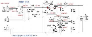
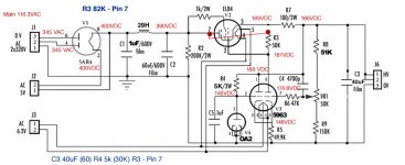
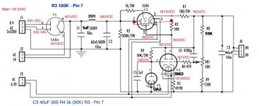
At min voltage output and min current output the voltage drop across R3 will be at maximum. At max voltage output and max current the R3 drop will be a minimum. You need a resistance value which can cope with both these extremes, while V3 RH has between 0.5mA and 2.5mA current. This is not a magic value, my guess is that a 2:1 range will do. Or just try 68k, 82k, 100k.
Calculate the max and min output voltages, from the potential divider on V3 RH grid. Measure the max and min voltages across C2 at min and max output current. EL84 grid will be a bit below output voltage, say 15V down.
At min voltage output and min current output the voltage drop across R3 will be at maximum. At max voltage output and max current the R3 drop will be a minimum. You need a resistance value which can cope with both these extremes, while V3 RH has between 0.5mA and 2.5mA current. This is not a magic value, my guess is that a 2:1 range will do. Or just try 68k, 82k, 100k.
For the sake of improving DIY understanding I will use the pot and set it to different values and continue to measure. I appreciate your patience. While this is a steep curve for me I provide help to others in other things outside audio where I have a better skillset and always have to take a deep breath and explain things several times. So I know how frustrating it can get when I'm on the other end.
DF96 -- In thinking about it maybe the best way for me to study what's happening is to try all three values and take readings then submit them here.
If you could be so kind to say 'no this value isn't working' while this value is working because its balancing... That would be very educational at least for me and maybe aardvarkash10.
Would you be willing?
If you could be so kind to say 'no this value isn't working' while this value is working because its balancing... That would be very educational at least for me and maybe aardvarkash10.
Would you be willing?
- Status
- This old topic is closed. If you want to reopen this topic, contact a moderator using the "Report Post" button.
- Home
- Amplifiers
- Tubes / Valves
- Oscillating PSU above certain voltage