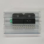
I bought two units of the LM3886TF chip here in Brazil for around $32.00 each.
It was very difficult to find...
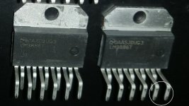
I've seen several photos of original chips on this site, these mine look very much like originals, they are up to all datasheet standards.
Any thoughts on its appearance and originality?
It was very difficult to find...
I've seen several photos of original chips on this site, these mine look very much like originals, they are up to all datasheet standards.
Any thoughts on its appearance and originality?
Attachments
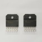
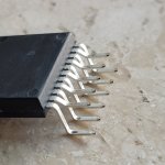
They look genuine from what I can tell. But the also look like they were de-soldered from a PCB. There's still thermal grease residue on the back (that's why it's greyish white) and you can see a line on the pins where the solder has been reflowed. That's a bit disappointing given the price paid.
Tom
Tom

I really appreciate your work, if I didn't live so far away and it wasn't difficult to import things to Brazil, I would buy your boards, but your website is a great inspiration.They look genuine from what I can tell. But the also look like they were de-soldered from a PCB. There's still thermal grease residue on the back (that's why it's greyish white) and you can see a line on the pins where the solder has been reflowed. That's a bit disappointing given the price paid.
Tom
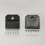
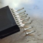
I found several photos on the site of specimens and they all have marks on the terminals, I believe it's because of the machine that makes the folds...
I am convinced that they are original and new.
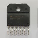
This is one of them, in the topic it says it came from Mouser:
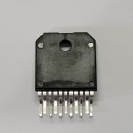
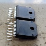
 There are also no marks of screws on the case or any type of support to fix a heatsink:

I'm going to start developing a scheme that meets what I need.
I am convinced that they are original and new.
This is one of them, in the topic it says it came from Mouser:
I'm going to start developing a scheme that meets what I need.
Attachments
Ah. That makes sense. You might be right about the marks on the pins as well. Things always look more dramatic under magnification. The inner row of pins (the even numbered pins) all show the original solder finish.I think the impression of thermal paste residues is due to the lighting.
I do ship to Brazil, but yeah, the process on your end is onerous to say the least. I'm glad you found inspiration on my website, though. Best of luck with your project.I really appreciate your work, if I didn't live so far away and it wasn't difficult to import things to Brazil, I would buy your boards, but your website is a great inspiration.
Tom
I thought the 3886 was always plastic case while the 3875 was metal tab? I don't like the look of those pins. They look to be scraped or perhaps pulled out of a socket. Is there even a socket available for the 3886/3875?I found several photos on the site of specimens and they all have marks on the terminals, I believe it's because of the machine that makes the folds...
I am convinced that they are original and new.
This is one of them, in the topic it says it came from Mouser: View attachment 1173293 There are also no marks of screws on the case or any type of support to fix a heatsink:
View attachment 1173294
I'm going to start developing a scheme that meets what I need.
As you can see in the LM3886 data sheet, there are there versions. They all have the same die inside. The differences are in the package.
LM3886T/NOPB - Metal back, lead-free solder
LM3886TF/NOPB - Plastic package, lead-free solder
LM3886TF - Plastic package, leaded solder
They're functionally identical for the DIYer. Just remember to use a thermal pad and shoulder washer to isolate the metal-back version from the heat sink.
Tom
LM3886T/NOPB - Metal back, lead-free solder
LM3886TF/NOPB - Plastic package, lead-free solder
LM3886TF - Plastic package, leaded solder
They're functionally identical for the DIYer. Just remember to use a thermal pad and shoulder washer to isolate the metal-back version from the heat sink.
Tom
I'd go with the TF/NOPB unless you're restricted to a smaller heatsink and need the increased thermal conductivity of the uninsulated version. I've never had a heat problem with these units and listened to one version at ~+/-32V with both chips simply held onto a 3/16" aluminum plate (4" x 5") with a pair of 2" spring clamps for a year or two, usually at volume. The only GC in current use here has the chips (TF) bolted to back panel of an old fire alarm control can (steel) and all is well. I'll fire it up and check temps out of curiosity.
I bought a couple stereo 3886 modules off of alibaba a few years ago. One is fine, one blew smoke after a few hours use with a hole blown in the case. Didn't change a thing and put the other unit in it's place. Cost per stereo amp was about the same as a single 3886 from DK or Mouser. Cheers
I bought a couple stereo 3886 modules off of alibaba a few years ago. One is fine, one blew smoke after a few hours use with a hole blown in the case. Didn't change a thing and put the other unit in it's place. Cost per stereo amp was about the same as a single 3886 from DK or Mouser. Cheers
I'd go with the TF/NOPB unless you're restricted to a smaller heatsink and ...
Thanks for the clarity. How are your speakers protected from these chip amp disasters.
Nothing more than Hope I'm afraid. My only two chip failures have been an LM4780 on initial testing before even seeing a test speaker and that alibaba 3886 module which was also shortly after power up. It was mounted in the FA can I mentioned, blew up and was replaced with the other and no problem.
I still have the thing in the shop. Maybe I'll be bored enough to troubleshoot it one day.
I still have the thing in the shop. Maybe I'll be bored enough to troubleshoot it one day.
The protection circuitry is called SPiKe™ by National (now TI) - this stands for Self Peak instantaneous Temperature (°Ke) (sic) and will protect the amp from almost anything. Although in theory this is a good thing, it's not so good when the protection circuits operate, so make absolutely sure that the amp is only used in applications where clipping/ overload can never occur, or is relatively lightly loaded. --- Rod Elliot Project 19
? if the 3886 amp is protected does that mean the spkrs are safe.
Project 127 uses TDA7293 which is has more robust protection but less complicated.
The vintage NAD 320BEE which I am repairing again has thermistors on the heatsinks and a control circuit to open the spkr relay.
? if the 3886 amp is protected does that mean the spkrs are safe.
Project 127 uses TDA7293 which is has more robust protection but less complicated.
The vintage NAD 320BEE which I am repairing again has thermistors on the heatsinks and a control circuit to open the spkr relay.
That built in protection is ONLY for thermal overload protection. It will keep the chip from self destructing due to high operating temps (for a while anyway). It may offer limited protection from overvoltage by reducing the front end bias to zero, effectively turning it off during a short term event. Long term high operating temps are still not good for it and will eventually fry it. WHEN that happens the protection fails too, and you could end up with DC to the speaker. If the speaker being used can’t handle that, then you must provide protection. At the voltages I tend to run chip amps, a 12” speaker can often take the full DC supply voltage for long enough to get to the power switch. A little 4” woofer with a 3/4 inch VC might not fare so well. If using it for a tweeter amp (which is a common use), just use a blocking cap with a pole frequency of a few hundred hz.
Well, it seems chip amps have more risk of speaker damage compared to discrete circuits and risk increases with loud music. ESP recommends to operate at less than optimal power supply voltage. And there is an option for MOSFET relays.
I am uneasy with this risk .. something must be done. There are iffy speaker protection modules on Amazon, eBay, and such for $10. Neurochrome has an inline mosfet module for $100 per speaker.
Do chipamp fans include or consider speaker protection in their DIY plans.
I am uneasy with this risk .. something must be done. There are iffy speaker protection modules on Amazon, eBay, and such for $10. Neurochrome has an inline mosfet module for $100 per speaker.
Do chipamp fans include or consider speaker protection in their DIY plans.
From looking at that LM3886 datasheet "SPIKE" waveform (I first saw it many years ago and it alarmed me) I'd worry about tweeters. It's clearly got a lot of high energy high frequency stuff that could cook tweeters, and be bad for ears as well. The "good" part is the DV/DT of the thing switching off looks much higher than any "true" audio signal, so it should be easy enough to detect when it happens. I want that detection circuit to instantly activate the MUTE input for a few seconds or maybe longer so the chip will cool down a little bit.
You can always measure average power (over say half second interval) and have it go to mute until it “clears”. You want to keep a tweeter at 5 watts average, regardless of where the overload originates.
Mosfet schmosfet. At this power level an ice cube relay (the ones with 0.25” fastons) is NOT going to fuse the contacts shut! It’s not capable of delivering enough energy, even with a shorted output transistor. The ones the size of your thumb nail, yeah. And IRF1407 mosfets are big enough anyway and don’t cost squat. You don’t need the $20 200V TO-247’s with .0005 ohm Ron. Its an LM3886 on less than 40V rails, not a kW pro touring amp or Mark Levinson that will drive a welding rod.
Mosfet schmosfet. At this power level an ice cube relay (the ones with 0.25” fastons) is NOT going to fuse the contacts shut! It’s not capable of delivering enough energy, even with a shorted output transistor. The ones the size of your thumb nail, yeah. And IRF1407 mosfets are big enough anyway and don’t cost squat. You don’t need the $20 200V TO-247’s with .0005 ohm Ron. Its an LM3886 on less than 40V rails, not a kW pro touring amp or Mark Levinson that will drive a welding rod.
- Home
- Amplifiers
- Chip Amps
- Originality of the LM3886TF