Tomorrow I will solder the components (up to the current assembly point - nothing is finished yet!) and test the circuit for the very first time - define R9 and C6. C1A to C1D will be done at the very end, after the input capacitance of the functional circuit has been determined.
Let's wait for the final result before we release the fire for the overkill version, what do you think @catd ? After all, the quick idea of a simple EQ should be able to compete with the pearl3 !
Hopefully the Asian production facilities have also produced the through-hole plating in an exemplary manner, otherwise I'll have problems - because now you can't solder anything from the component side.
greetings,
HBt.
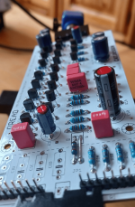
No difficulties with soldering
The capillary effect pulls the solder upwards ..!
"But could it be that the general interest in our project is approaching zero?" .
.
The capillary effect pulls the solder upwards ..!
"But could it be that the general interest in our project is approaching zero?"
.Attachments
Don´t you think, it has something to do with "timing"??"But could it be that the general interest in our project is approaching zero?"
I mean..... the P-3 has "just" been released, lot of interrested builders are not finished yet...
Just my 2 cents
That could be the case, my P3 is still a long way from being finished - maybe at the end of the year. I'll finish the "Chestnutspread-Gedenk-EQ" before then and then maybe start the "Supra2024" or just the P3, but the problem is: I've basically already finished a kind of P3 - albeit with a different input stage than Wayne's big hit.
kind regards,
HBt.
kind regards,
HBt.
Fire free
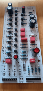
Our joint "simple RIAA-EQ" passed the first test with flying colors.
Statically:
everything is fine, all DC working points are as expected.
-VCC = -9.9Vdc
+VCC = 9.9Vdc
Soft start -> approx. 5 seconds; resulting in +/- 9V rails.
Dynamic:
with R9=47Ohm and C6=2.2nF ceramic and in parallel to R7=1k2Ohm a small compensation C with 18pF ceramic (together they prevent a 10MHz oscillation, at least on my board and the Overkill version) the following fast data results.
Input capacitance C_ip = (60pF plus a line section RG 174 with 15pF) 75pF.
Well, this is our most extreme assembly - so you shouldn't be surprised about a rather large parallel capacitance.
Output resistance, impedance at f=1kHz and u_o > 400mVrms approx. 76.6Ohm.
Maximum undistorted excursion 14Vpp, without external load at f = 1kHz.
Maximum output voltage 8.2Vpp at 50Hz and a load of 10kOhm. As long as Rload remains >= 10kOhm, we can dispense with an impedance converter on the output side as already predicted, otherwise not!
All we need now is a housing and a listening test.
I wish you lots of fun and enjoyment with this small, discrete EQ.
Bye,
HBt.
Measuring devices used:
HC-5010EC
MIC-4070D
LCR-400
HM8018
Keithley 2015 THD
HM407
HM8030-6
and WSS1986-PSU
Pencil, calculator, eraser and various load resistors.
Attachments
Last edited:
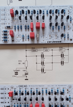
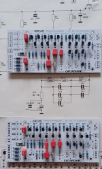
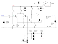
If there is still a need for clarification, I will use the attached schematic with its nomenclature.
Notes on the current state of affairs:
C7 can be omitted as well as the 16 discrete setting options for C_inp (here formed by cat's C1A,B,C,D). It makes little sense if in the overkill variant our input capacitance is already (with wiring) <100pF, with really bad luck the value is much greater than 100pF - but don't panic.
You are welcome to test the symmetrical power supply, but it is definitely not necessary, well, the board provides for it - let's just try it, but then I would also connect R1 and R2 in parallel and to ground, away from the rails.
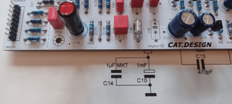
C3 (&C15 cat's) also want a 7.5mm pitch, C10 definitely likes a parallel 1µF film capacitor as an assistant.
If we are satisfied with the final sound result and have not forgotten R11=220kOhm, then we solder a 100nF MKT / MKS and a 10nF FKP film capacitor in parallel to our coupling capacitor C2 & C1 = 47µF / 63Vdc types each (but it doesn't have to be, it's all about the so-called DA and the ESR) ..!
For frequency response compensation (the phase reserves) we try the wooden hammer method (there is no other way to call this method than with a wooden hammer - it works better) and solder either a small ceramic disk capacitor in parallel to R7 (18pF) or perhaps a 10pF between point b and point c, i.e. de facto in parallel to our RIAA network.
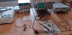
In order to be able to see oscillation tendencies and all possible other interferences, deformations and spontaneous oscillations on the edges of the actual useful signal, you need an analog oscilloscope - perhaps a nice old "Tektronix". The cheap DSOs are not suitable for this.
Statically everything is fine, the first stage shares 203.2µA per pair, a total of 1.016mA flows in the left (507µA) and right (507µA) branches. The second stage is very similar, where the pairs share 699.1µA and both branches are perfectly balanced with equal currents, adding a further 2.097mA in total. The total quiescent current requirement is 3.12mAdc -> 56mW per channel; almost ideal for battery power.
Notes on the current state of affairs:
C7 can be omitted as well as the 16 discrete setting options for C_inp (here formed by cat's C1A,B,C,D). It makes little sense if in the overkill variant our input capacitance is already (with wiring) <100pF, with really bad luck the value is much greater than 100pF - but don't panic.
You are welcome to test the symmetrical power supply, but it is definitely not necessary, well, the board provides for it - let's just try it, but then I would also connect R1 and R2 in parallel and to ground, away from the rails.
C3 (&C15 cat's) also want a 7.5mm pitch, C10 definitely likes a parallel 1µF film capacitor as an assistant.
If we are satisfied with the final sound result and have not forgotten R11=220kOhm, then we solder a 100nF MKT / MKS and a 10nF FKP film capacitor in parallel to our coupling capacitor C2 & C1 = 47µF / 63Vdc types each (but it doesn't have to be, it's all about the so-called DA and the ESR) ..!
For frequency response compensation (the phase reserves) we try the wooden hammer method (there is no other way to call this method than with a wooden hammer - it works better) and solder either a small ceramic disk capacitor in parallel to R7 (18pF) or perhaps a 10pF between point b and point c, i.e. de facto in parallel to our RIAA network.
In order to be able to see oscillation tendencies and all possible other interferences, deformations and spontaneous oscillations on the edges of the actual useful signal, you need an analog oscilloscope - perhaps a nice old "Tektronix". The cheap DSOs are not suitable for this.
Statically everything is fine, the first stage shares 203.2µA per pair, a total of 1.016mA flows in the left (507µA) and right (507µA) branches. The second stage is very similar, where the pairs share 699.1µA and both branches are perfectly balanced with equal currents, adding a further 2.097mA in total. The total quiescent current requirement is 3.12mAdc -> 56mW per channel; almost ideal for battery power.
Attachments
Last edited:
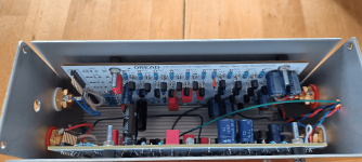
Short info:
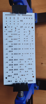
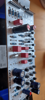
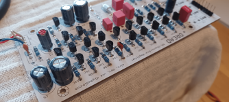
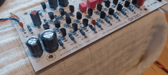
I have completed a circuit board.
So far everything is fine except for the same output swing you mentioned, here at 16MHz, 5mVpp.
I put the board in a closed metal box connected to ground and the oscillation completely disappears, even without installing a capacitor.
So no problems are to be expected when operating in a suitable housing.
quick and dirty
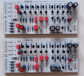
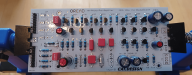
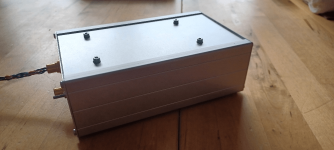
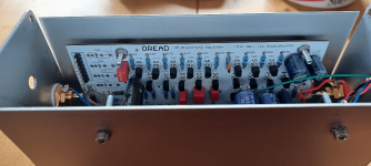
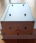
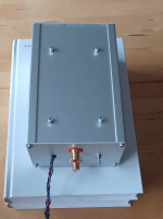
Ok - I quickly inserted both boards into a standard aluminum housing today. However, the fiddling is no fun at all, no matter, that's where our project will live for the time being - testing.
Which version did you build @catd ? Overkill, PNP-NPN-PNP or NPN-PNP-NPN; for which (dimensioning depending on the) operating voltage ?
Attachments
Maybe rename the project in a new thread? "Oread Outcome" or something, since OP hasn't had time to direct.Don´t you think, it has something to do with "timing"??
I mean..... the P-3 has "just" been released, lot of interrested builders are not finished yet...
Just my 2 cents
Cheers!
The MM input:
First, R11 (with the original 220kOhm) should be increased, 270kOhm or even 330kOhm ---> I measure 44.4kOhm||69pF in the overkill setup with +/- 9Vdc operating voltages.
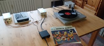
The first sound impression:
Practically zero noise, I have to turn my headphone amplifier all the way up to be able to guess anything.
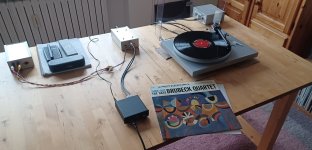
The Brubeck Quartet comes across as extremely black, natural and abysmal, with absolutely no distortion whatsoever.
Madness ...
As if it were a tube, so black - black is beautiful.
@MarcelvdG
Dear Marcel, no shot-noise audible / nothing.
Kind Regards,
HBt.
First, R11 (with the original 220kOhm) should be increased, 270kOhm or even 330kOhm ---> I measure 44.4kOhm||69pF in the overkill setup with +/- 9Vdc operating voltages.
The first sound impression:
Practically zero noise, I have to turn my headphone amplifier all the way up to be able to guess anything.
The Brubeck Quartet comes across as extremely black, natural and abysmal, with absolutely no distortion whatsoever.
Madness ...
As if it were a tube, so black - black is beautiful.
@MarcelvdG
Dear Marcel, no shot-noise audible / nothing.
Kind Regards,
HBt.
Attachments
Dear Markus,
thank you very much for your intervention, your interest and above all your layout - your circuit board. Without you, the project would have died long ago. I hope that your component dimensioning from the E6 and E12 series for a symmetrical operating voltage of +/- 15Vdc works just as well in practice as my original suggestion, which is not necessarily a matter of course or automatically given - and is also remotely related to Marcel's original and legitimate objection.
"Fire away"
HBt.
Thank you very much,
but evolution is progressing and at this point development is not yet complete - it's just the beginning and it could end up being the case that everything up to now is discarded.
Without modulation, I can definitely hear a few regular sparks, they are not masked by the other noise - but really only when listening analytically into the background noise, with the headphone amplifier turned up all the way.
So the motivation is: the little sparkles may still disappear (but they don't have to, so don't panic!).
.
greetings,
HBt.
but evolution is progressing and at this point development is not yet complete - it's just the beginning and it could end up being the case that everything up to now is discarded.
Without modulation, I can definitely hear a few regular sparks, they are not masked by the other noise - but really only when listening analytically into the background noise, with the headphone amplifier turned up all the way.
So the motivation is: the little sparkles may still disappear (but they don't have to, so don't panic!).
Not a bad ideaMaybe rename the project in a new thread? "Oread Outcome" or something, since OP hasn't had time to direct.
Cheers!
.greetings,
HBt.
A word about C7, R11 & C2
C7 can now really be omitted if you consider the usual line capacitance of our connections - omitted because the input capacitance of the overkill proband is already <100pF.
R11 is obviously too low impedance, the current dynamic input resistance of the differential amplifier is (without R1 || R2) approx. 764kOhm - therefore R11 from the E48 or the E69 series should be selected with 301kOhm, or 309kOhm if we want to provide the obligatory 47k that our MM generator sees.
C2 is 47µF, taken straight from the component box, and could also be 4.7µF as an electrolytic capacitor - but no smaller (this has something to do with its contribution to the overall distortion, not with the lower cut-off frequency of our entire EQ).
But C2 can do more than just inject; it could set a lower cut-off frequency at the beginning of the signal processing. As an MKP or FKP or Mundorf special, with >470nF it sensibly defines the beginning of our transmission range.
Now that I've listened to three different genres (records) with two different sets of headphones, what's the next step?
I will vary the operating voltages in their value, observing the behavior of the current state of our common and public development "Oread-MM-approach". Perhaps the tiny sparks will disappear or the sound character will change in one direction or another?
Furthermore, we naturally assume that our input impedance with its Rp and Cp, i.e. its real and imaginary part, is constant over the whole frequency-range.
But this is definitely not the case, a metrological determination must show the course. So there are still some metrological investigations to be done, long before we start showing off THD curves ...
HBt.
the beginning
It all started with the figure of "Haudegen" in his thread. Let's sort it out briefly:
simple, compact and actively equalized in one step
the design should be rebuild-proof, but also a little more interesting than just the standard solution with an NE5534.
This is how we came up with the familiar discrete OP with five BJTs a jFet was not allowed for some unknown reason
finally, I suggested to the "chestnut" to start with the well-known negative feedback network (a thing that is nothing more than a frequency-dependent resistor) the basic intention was - to tinker freely, to follow findings, i.e. mistakes can be made - we want to learn something.
In this sense, it could continue until a final edition of the dwarf Oread (not Laurin) outcome.
Thats all,
HBt.
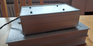
A good record for afternoon coffee
Oboe concertos by Vivaldi, Marcello and Platti, while OREAD is operated with +/- 6V to +/- 12V in the core - Sennheiser's HD555 over the ears.
Zero problems, tonally everything paletti - noise or other disturbances only recognizable far after 14 o'clock, guessable. Here everything is already covered and completely masked by the imperfect medium of vinyl, the oboe (played by Bruce Haynes with the Baroque Orchestra conducted by Frans Brüggen) suddenly emerges from the silence.
Conclusion:
The current OREAD also rocks the quiet tones.
- Home
- Source & Line
- Analogue Source
- Oread - a DIY MM phono approach