
Even if i replace floating smps with 2 x 9v bat, still noisy.
Even if i remove inductor from pcb (at about 20cm), noise is still the same...
Even if i put a more decoupling caps for vcc (ceramic, mkt, etc) ...
Even if i put rc snubbers; scottky antiparalel diodes, adjusting deadtime, etc... still the SAME noise...
6N137? ... i don't know...
Even if i remove inductor from pcb (at about 20cm), noise is still the same...
Even if i put a more decoupling caps for vcc (ceramic, mkt, etc) ...
Even if i put rc snubbers; scottky antiparalel diodes, adjusting deadtime, etc... still the SAME noise...
6N137? ... i don't know...
I think there is no way around some detailed Jitter measurements.
Does you scope offer something like a 1:10 time base magnifier? What you need is the possibility to trigger
on one edge of the comparator output and watch the next following edge of the same direction. You need to do this with a time basis of 10ns.
Then simply step through the entire circuit.
Always trigger to the comparator output and watch the next edge with the second chanel at:
Comparator output, level shifter output, driver outputs, half bridge output.
You will find some jitter which is getting larger step by step. With some good luck you will find one stage, which is dominating the jitter.
Is the noise really sounding like white noise?
Jitter tends to sound slightly more nervous, less continuous.
Please note already 10ns random Jitter are audible. Imagine your period might be 4us (?). Then 10ns are already 1/4000, means -72db of full power....
How loud is your noise? In which distance of the tweeter can you hear it, without music? 10cm? 50cm?....?
BTW:
It should theortically work to see the jitter even at same edge to which you might trigger.
...except the comparator jitter of course.
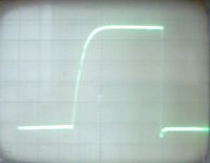
But you should find the jitter errors of all follwing stages. Ideally the edges should have a constant delay vs. the comparator output, but in reality they will vary a little bit. A analogue scope displays this very nice by a thick unprecise looking edge.
It should theortically work to see the jitter even at same edge to which you might trigger.
...except the comparator jitter of course.
But you should find the jitter errors of all follwing stages. Ideally the edges should have a constant delay vs. the comparator output, but in reality they will vary a little bit. A analogue scope displays this very nice by a thick unprecise looking edge.
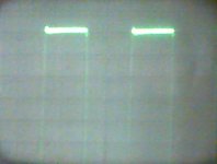
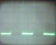
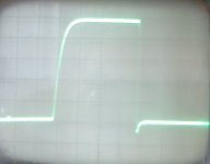
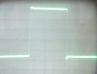
Measurements taken before without modulator sch. Only power stage, 250 kHz clock 50% and deadtime generator with logic gates HCT series with value shown in my sch (post 3)
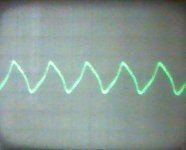
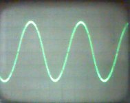
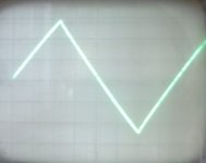
Here is my measurements on closed feedback loop (with LM319 comparator, feedback after the filter)
Triangle generator (1v/0.5us):
Here is my measurements on closed feedback loop (with LM319 comparator, feedback after the filter)
Triangle generator (1v/0.5us):
Attachments
- Status
- This old topic is closed. If you want to reopen this topic, contact a moderator using the "Report Post" button.
- Home
- Amplifiers
- Class D
- optocoupling power stage - hiss with 6N137