Yves,
If you go further than Caly, all the way to Seattle, you should PM me and come by for a visit. We can always eat cherries and swap lies....
Sheldon,
If you want to explore even higher performance than what you have, which is the initial design from the RDH, you might try splitting the primary wire sizes in half and essentially winding two coils in one.
Pri A1
Sec 1
Sec 1
Pri A2
Sec 2
Sec 3
Pri B1
Sec 1
Sec 1
Pri B2
Pri A & B are paralleled. The three sec sections hold the 4 ohm single layer, paralleled windings, in sections one and three and have the 2nd section for 8ohm and 16 ohm. If you drop the numerical wire size by one AWG size for Pri B2, the two paralleled halves A1+B1 and A2+B2 will be matched for DCR within about 1 ohm.
Yvesm said:You will probably obtain better (if really needed) hi freq response by splitting the primary so that the first and the last section be half the thickness of the inner one.
I suppose you already tried to use "SPLIT" button in the green area ?
Thanks Yves. Yes, I did split to get twice the thickness for the middle primary layers. I just attached the wrong image. Everything else is the same though.
We live in north San Diego now, but lived in Ventura for a few years. I really like that area and north. Check out the surf at Rincon for me when you drive by.
Sheldon
BudP said:Yves,
If you go further than Caly, all the way to Seattle, you should PM me and come by for a visit. We can always eat cherries and swap lies....
Sheldon,
If you want to explore even higher performance than what you have, which is the initial design from the RDH, you might try splitting the primary wire sizes in half and essentially winding two coils in one.
Pri A1
Sec 1
Sec 1
Pri A2
Sec 2
Sec 3
Pri B1
Sec 1
Sec 1
Pri B2
Pri A & B are paralleled. The three sec sections hold the 4 ohm single layer, paralleled windings, in sections one and three and have the 2nd section for 8ohm and 16 ohm. If you drop the numerical wire size by one AWG size for Pri B2, the two paralleled halves A1+B1 and A2+B2 will be matched for DCR within about 1 ohm.
Thanks Bud, I'll ponder this one a little, until I get all the secondary connections right.
Sheldon
Yvesm said:Found two papers from Crowhurt here:
http://www.audiofaidate.it/materiale/20_030_040_001_crowht_outtrafoI.pdf
http://www.audiofaidate.it/materiale/20_030_040_001_crowht_outtrafoII.pdf
Yves.
Great papers, aren't they ?
Seems that were the last kept secret of those black-art magnetic guys. Was not easy to found, but worth all the time spent to get a copy.
Yes, but not with the same clarity and completeness.
Note that there is more than the split-section primary in this paper, but some rules and graph to design the transformer for the tube to achieve the best bandwidht at minimum cost.
There are also some valuable articles on MJ (but in japanese!) about the winding scheme for Hashimoto transformer. That is a smart way to get the best compromize between leakage inductance and winding capacitance. I already asked help to have a translation of the article on this forum, but till now without success. Good time to ask to some Japanese friend of diyuadio to help the worldwide diy audio community.
Please post and translate the articles on MJ Feb 2002 Issue, Page 133.
Sheldon said:The first transformer I made had a hf roll off around 60kHz, and very nice 10kHz square wave - nice shape and just a little ringing. I didn't do a very good job of getting the margins for the secondaries, as described by Bud. They tended to cover the bobbin end to end. I got better on the second wind, and everything was a little neater. But the performance was worse - 41kHz roll off. OK, let's try a third, neater still. This one had the 3dB corner at about 35kHz.
Here's an interesting finding (probably no surprise to Bud), that I also reported in my amp thread.
I didn't pot the bobbins, but applied shellac to the windings as I proceeded. And I wound each and finished it up in the same day, so the shellac was not completely dry. The first transformer had been sitting a few days before testing, the second was tested the day after it was made. Now a month later, both transformers give the same -3dB point of around 65k. I was surprised to find that a few day difference in curing made a significant difference. Not surprisingly, the 10k square waves look very similar too now (and good, just a little ringing visible as a slight ripple on the top and bottom).
So, winding technique seems not the issue, but potting and cure apparently is.
Sheldon
Re: Coke design
More or less ! ! !
Deliberatly use a very lo Z secondary and force it's diameter very small so it will not affect the available space for the copper.
And interleaving as no sense, set for only one section.
Of course, the only valuabe results are the primary resistance and its inductance according to its turns number, wire dia, DC component and gap height.
Yves.
Tyimo said:Yves!
Is it possible to design a choke with your OPT design software?
Could you give me some help?
Greets:
Tyimo
More or less ! ! !
Deliberatly use a very lo Z secondary and force it's diameter very small so it will not affect the available space for the copper.
And interleaving as no sense, set for only one section.
Of course, the only valuabe results are the primary resistance and its inductance according to its turns number, wire dia, DC component and gap height.
Yves.
Re: Re: Coke design
while we are at it - do you mind writing few lines - what's important in making load chokes (both plate and grid ones ) ?
TIA
Yvesm said:
More or less ! ! !
Deliberatly use a very lo Z secondary and force it's diameter very small so it will not affect the available space for the copper.
And interleaving as no sense, set for only one section.
Of course, the only valuabe results are the primary resistance and its inductance according to its turns number, wire dia, DC component and gap height.
Yves.
while we are at it - do you mind writing few lines - what's important in making load chokes (both plate and grid ones ) ?
TIA
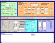
EL84 PP OPT
Hi Yves!
Could you give me some help to design a PP OPT for EL84?
8K, 20Hz, 15W on SM85B
I am a bit confused, because when I calculated the OPT with the classical methode I got ca. 3200 turns for the primary, but when I was simulating it with your program I got much better results with ca.2400 turns.
I don't know in which one should I trust....
Greets:
Tyimo
Hi Tyimo.
This core have dimensions very similar to 40mm of EI96 lams !
Here is my guess, here is why:
-1 Keep primary turns as low as possible as long as the B total doesn't exceed 1.5 Tesla for the max power combined with the lower frequency.
This drastically reduce leak inductance allowing for a simple interleaving scheme.
-2 Reduce parasitic caps using thick insulation between sections (here 0.8mm cardboard) and between primary layers (0.2mm cardboard). Don't use mylar wich exhibit higher dielectric constant (with pentodes, even feedbacked, I feel that keeping parasitic caps low is more important than low leakage inductance).
Keep an eye on Fo (the resonnant frequency due to the combination of leakage inductance and shunt cap.
Keep the other on the resonnant frequency of each primary section that is shown by "left clicking" on it in the central horizontal yellow zone. Increase ILThick to push'em above the previous one.
Then play with wires diameter for best filling (full layers) while keeping another eye on losses and bobin over filling.
Some iterations may be necessary
Here are my rules, only mines ! You have not to agree with
Yves.
Attachments
The earlier links to the Crowhurst xfmr winding articles don't seem to work anymore.
http://www.diyaudio.com/forums/tubes-valves/109165-opt-design-assistante-el84-8.html#post1337112
Anywhere these articles are still available?
http://www.diyaudio.com/forums/tubes-valves/109165-opt-design-assistante-el84-8.html#post1337112
Anywhere these articles are still available?
Hi Yves!
Thank you very much!!!!!
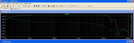
I made the simulation with the LTSpice and its looking very promising!!
One more question:
Is the wire diameter a Neto or Brutto value in your program?
Thanks your help!!!!
Thank you very much!!!!!
I made the simulation with the LTSpice and its looking very promising!!
Is the 1.5 Tesla not too high for this iron? I know the C-cores can go higher than ordinary EI, but I thought ca. 1.2 Tesla is the limit.1 Keep primary turns as low as possible as long as the B total doesn't exceed 1.5 Tesla for the max power combined with the lower frequency.
One more question:
Is the wire diameter a Neto or Brutto value in your program?
Thanks your help!!!!
Attachments
I routinely use 1.4 for GOSS EI lams.Is the 1.5 Tesla not too high for this iron? I know the C-cores can go higher than ordinary EI, but I thought ca. 1.2 Tesla is the limit.
Considering that C core are made with a bit thinest foil (0.3mm rather than 0.35) and that grains are all correctly oriented unlike in EI, I beleive that 1.5T is rather conservative
Remember than this occurs only for the improbable combination of full power (15W) at 20 Hz
Grade 1 insulated copper is assumed.One more question:
Is the wire diameter a Neto or Brutto value in your program?
Yves.
- Status
- This old topic is closed. If you want to reopen this topic, contact a moderator using the "Report Post" button.
- Home
- Amplifiers
- Tubes / Valves
- OPT Design Assistante (EL84)