That it should be an (old version) BD zone free device...
I think this one was produced Q4 2012 or Q1 2013.
Never tested BD, but for sure cannot play ISO, and I would really like to play ISO...
Coris, as an OPPO expert can you advice preferred the voltage rating for the CE26,30,46 (reg input) on the audio board, pls. I believe 10V will be enough!
Also, as for your advice abode on the CE 5,34,12 (reg output cap) you mentioned it is better to pump up capacitance, but I have an idea that OSCON 6SEPC1500M (6,3V) might be more beneficial due to its high ripple and low esr spec with the capacitance just 1500uF.
One more finding on the motherboard..., you replaced SMD power caps with some OSCON through hole, just to share what I did find - 16SVPG330MCT-ND, yes lower than 470 you used, but the same SMD footprint and excellent spec. Someone might like the original fitment, like i do )
Coris, as an OPPO expert can you advice preferred the voltage rating for the CE26,30,46 (reg input) on the audio board, pls. I believe 10V will be enough!
Also, as for your advice abode on the CE 5,34,12 (reg output cap) you mentioned it is better to pump up capacitance, but I have an idea that OSCON 6SEPC1500M (6,3V) might be more beneficial due to its high ripple and low esr spec with the capacitance just 1500uF.
One more finding on the motherboard..., you replaced SMD power caps with some OSCON through hole, just to share what I did find - 16SVPG330MCT-ND, yes lower than 470 you used, but the same SMD footprint and excellent spec. Someone might like the original fitment, like i do )
Yes, 10v rating for the CE26,30,46 caps is alright. Also is alright 1500µ/6,3v for CE 5,34,12.
Well, I have replaced that caps on motherboard, but indeed, not just necessary. However, that caps should not have too large capacity, as it are on the DC/DC converters outputs. A too large capacity it can trigger the over current protection for that converters... At least is better not replace it. As I found out later, the improvements do not come from that caps, but from using a linear PSU to power that DC/DC converters (whole motherboard).
About the rectifier diodes, is not so important to be very fast, as it rectify 50Hz. The clue is to have there rectifier diodes with lower forward voltage drop. And Schottky type it have such low Vf... This it improve the ripple level.
Another clue is to use massive capacity right after rectifier diodes to minimise the ripple levels. Or best, using a pre regulator before DAC power rails regulators...
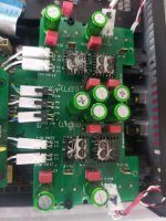
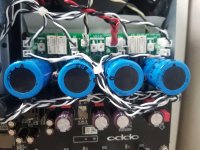
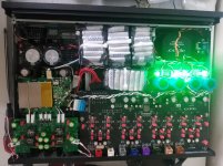
Just that latest Mods to this player
Base mods by Coris and my own IV board and IV charging/Power supply board, based on the Sen Project.
It sounds pretty good.
Base mods by Coris and my own IV board and IV charging/Power supply board, based on the Sen Project.
It sounds pretty good.
Attachments
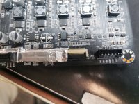
Interesting project. Congratulations! I have an observation about the battery on my clock board. I advice replacing it soon, as it seems to me inflated. I will suggest you use an LiPo battery of 1200mA/h (for drones use). The +/- wires it can be soldered directly on clock board - battery pads.
I’ve looking to see how many of these changes to the clock and filtering apply to the 205. I been using the 205 for streaming and it’s an improvement over the 105.
I have check to see if I/v still it bias wrong. Do intent change out the power supply SMP does not be long in audio gear. And dump the opamps for some 797 or 627 that I had.
I use to telecom design and the network clocks were always square.
i was hoping folks that have modified there 205 would jump in. My 105 in the closet just have sold it as I go back using it for streaming.
cheers
james
Thanks Coris, I new the supply was the a limit on performance. I was planning on using THF Tantalum caps they super low ESR at lower frequencies but the axial part. Mallory and Sprague had a version. I have them let over from may hardware days designing Seismic data acquisition systems. These are a little better than OSCON at lower frequencies.
What a day!?Hi Guys, please help to identify value R19, R17, R16 on the BDP105 mainboard, as per attached pic.
One of those resistor is 0 Ohm.
Thank you!
Need to know C70 CAP value ((( which is jump out of the tweezer
Bad luck ((
")
R2 resistor is not 50k, but (it should be) 100k and it is placed as load/termination for the DataCLK input signal/pin of the chip. This signal (component of the audio digital interface - input signals), is not the same as the main/master CLK signal/pin for the ES9018 chip. You should not modify anything on this pin, as then the DAC it may fail to function properly.
The clock input pin for ES9018 is the pin XI - 24 (see data sheet). You can inject a clock signal on this pin.
The clock input pin for ES9018 is the pin XI - 24 (see data sheet). You can inject a clock signal on this pin.
Last edited:
Thanks Coris for the info. All figured out and working fine.
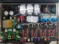
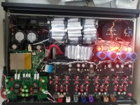
Some time ago I got my hands on Modwright 105D. Having all modified OPPO 95 with Lundahl transformers output stage, oscillators, LPSU etc, the Modwight was not really enjoyable in comparison. I'm trying to make it match my oppo 95 but all in all it'll most likely end up with Lundahl transformers output stage.

Some time ago I got my hands on Modwright 105D. Having all modified OPPO 95 with Lundahl transformers output stage, oscillators, LPSU etc, the Modwight was not really enjoyable in comparison. I'm trying to make it match my oppo 95 but all in all it'll most likely end up with Lundahl transformers output stage.
Looking at the pictured Modwright 105D, I wonder indeed how a such mess of wires and components placed all over in the tight place inside a device it may be called an upgrade... For many years ago, I did almost the same, but I found out quickly that this is definitely not the way to go in improving a device design and quality. Especially when doing such work for others... It is a difference indeed when one individual is experimenting and try to improve his own device, and when an established and declared (advertised) professional tweaker/upgrader is doing such a work.
What it surprise me, is that some "modders" are choosing to add one or another items, more modules, components or so, over the original design, instead of replacing and correcting what is wrong in that device original design or manufacturing process. Well, Oppo (as another producers as well) are not doing wrong things in such consumers products, but are forced to simplify, minimise and adapt the electronic design to the production low costs requirements of the financial department of that companies. I see as the modders task or goal the corrections of the original design, replacement of the cheap original components with the right ones, and so on. Adding more modules and processing more the mediocre quality signals out of an original design, it may not improve very much anything. Rather it may overall worsen the quality... Well, it is indeed more easy adding one or another, than replacing components on original boards, or modifying these boards. Much more work, but the right way of doing, and real results.
How can one expect improvements by adding a tube stage (and a bunch of components and long wires all over), while using the same sourced signals from a poor (cheap) original Oppo design? In above pictured device I see it still be used the same low quality original power suppliers approach (on stereo board), the same original components in the analogue signal processing, same poor quality power system around DAC chip, and so on... I can even see a kind of improvised module placed right over an unshielded toroid (maybe of an LPS inside). It is not about any interferences and brum in this case?! Just wondering...
Well, some of my considerations, out of the picture I can see here.
- Home
- Source & Line
- Digital Source
- Oppo's BDP105 - discussions, upgrading, mods...