No problem about your last posts...
Yes, indeed, damping the transport device it bring some noticeable improvements (when playback from discs).
There is a mechanical design problem with the discs player in 105 (as in the earlier models).
I think I have explained this in the 95 thread. This transport it is mounted in a very rigid meaner inside the player enclosure. Oppo used some quite powerful springs in a wrong meaner, thinking this way it will be some damping... The springs only press very heavy the transport enclosure to the player cabinet, in a very rigid construction. Here is the big clue to be done some modifications.
Such mod is quite complicated, but it may bring the best results. I have replaced the original springs with some silicon dampers fabricated for hard discs use. As a result, the transport in my player just float free, sitting on these silicon things.
You may try to find the description of this mod in the 95 thread, I think in the beginning of it. There are some pictures there too.
This mod is described here (actually in this thread):
http://www.diyaudio.com/forums/digi...o-s-bdp105-discussions-upgrading-mods-35.html
and here:
http://www.diyaudio.com/forums/digi...o-s-bdp105-discussions-upgrading-mods-34.html
http://www.diyaudio.com/forums/digi...o-s-bdp105-discussions-upgrading-mods-35.html
and here:
http://www.diyaudio.com/forums/digi...o-s-bdp105-discussions-upgrading-mods-34.html
Linear power module
I just installed the linear power module from Jae Hong Lee for the OPPO-105.
He describes it here: Jae H. Lee Blog :: OPPO 95, 105 and 105D LPM upgrade V. 3 and here: OPPOMOD - About
This is easily installed, and involves temporarily removing the multichannel board, and then permanently removing a support strut, and the original switching power supply for the digital board and the disc drive.
The unit is well-built, and uses the original cables for hookup.
After installation, disc playback especially seems improved, and in general the noise floor seems lowered.
Eric
After installation, disc playback especially seems improved, and in general the noise floor seems lowered.
Probably quite a nice add-on, but my argument would be that I am achieving the same and possibility better, at much lower cost. So I believe is Coris.
Where is the worst noise? Identify that - and it may not be where you think it is. The solution some of us are using absorbs noise generated by the DAC itself and also acts as a second order filter attenuating noise from the power supply as it LC, relying on some inductance feeding the C. Then the remaining problem would possibly be airborne, but use a zero-feedback post-DAC circuit that won't suffer slew rate problems, and you have all bases covered.
Admittedly, that last bit may not be low cost - but IMO the best choice, no opamps.
Cheers, Joe
.
Calling himself OPPOMOD - is that not a TM infringement?
.
I do not want discourage (give up) eganz1, but I will express my point of view regarding the switching PSU in Oppo player, and in general in a digital system.
Feeding a digital system with linear power is only positive, thinking the quality of the approach. But when a digital system use quite much current, the efficiency of a serial PSU degrade much in such case. The big cons of a serial PSU is its heat dissipation for important currents.
On the top of this cons it come another one, which it negate the benefits of a cleaner serial PSU. A digital system is noisy by its way to work. This is a very solid fact! The only way to reduce the digital system noises is filtering, and shielding the eventual EMI noise generators. So, using a serial PSU, one feed the system with a clean power for a very noisy device/load. Benefit/result = 0 (nonsense). More, one get quite much heat from the working serial PSU...
What is to be done (more reasonable)? Minimise the noise generated by the switching PSU itself. Long connection wires between the PSU and the targeted circuits, is just bad. This is the case of Oppo players. Long connection wires act as good emission antenna for the HF noises of the SMPU. Solution: better power rails decoupling, shielding of sensitive circuits, better filtering out the HF noises.
In the Oppo player case, the SMPU is meant to power the mother board of the player, and the CD/BR transport (which it need quite important currents). The analogue stage (lower current hungry) it use already a separate serial PSU. This approach of the design is very reasonable. So it have to be.
In my opinion, the only improvement one it may bring to the digital stage, powered by a SMPU, is to specially care of powering the oscillators with a very good (low noise) local PSUs. This exclusively clocks dedicated PSUs it may be a serial regulator, shunt regulator, battery. The impact of cleaner power for the system clocks is quite high for both audio and video stages of the player.
I still think that the SMPU in Oppo is in the right place. Only some corrections it may be done to lower the SMPU EMI noises, even more. For production reasons, Oppo did not paid attention to such details...
Else, I think Oppo Company should react when somebody use its marketing name, to promote another or himself products... Or OPPOMOD it may have the right permission from the Oppo Co.? Anyway, this is another story and not our business...
Last edited:
I do not want discourage (give up) eganz1, but I will express my point of view regarding the switching PSU in Oppo player, and in general in a digital system....
Hi Coris, pretty much agree with all you just said. Cheers, Joe
.
Coris,
The linear power supply runs cool. It has a heat sink inside which also wraps around the bottom and touches the bottom of the case. I added some Arctic Silver thermal interface material to couple the heat sink to the bottom of the case.
I wanted a solution that was easy and quick to install, as I didn't have time to goof around with the SMPS.
Eric
There is a careful magazine review of the effect of this Linear power supply modification by itself on a stock OPPO-103 here in French: Test alimentation linéaire régulée Oppomod pour platines Oppo 93/103 et 95/105 | CineHomeDigital
they conclude that it has a significant improvement to both audio and video for the 103.
they conclude that it has a significant improvement to both audio and video for the 103.
Last edited:
Coris,
The linear power supply runs cool.
It sounds like it has been well done.
.
Here is my solution for battery powered clock(s) for Oppo (including some other applications...).
This board it were designed to be used on Asus ST/STX sound cards (it fits actually mechanically with ST/STX). But it can be also used on what so ever system. I will use it for Oppo players (3 clocks)... It can be populated with, and it can power up to 4 oscillators of different foot prints. Clock signals transported by 0.8 mm coax.
A new and improved design of this board is in production now. The new board it will have accessible pads from the pin 1 (Enable) of all the 4 oscillators, as a simple start up delay circuit, in case it will be necessary for a more precise control of the clock signal in conjunction with the host system power up sequence.
One may note that as it is this circuit, there exist a delay for clock signal start induced by the relay itself. There is about something into 15-20ms, depending of the relay construction/specification. If this delay it may not be enough for a host system power up sequence, then the Enable pin of the oscillators have to be used accordingly. The new (upcoming) board provide access to the Enable pins of the oscillators, to be connected further to the host system. Or these Enable pins it can be connected individual or all together to a simple delay circuit on board.
The battery charging circuit it can be connected to a 9-12v DC, or to 5v DC rails, depending on the host system. When is to be connected to a 5v rail, the 7805 regulator on board have to be bypassed (shorting its in/out pins). A gap on the traces is provided for this task. Charging current is limited to 400mA, and monitored by a specialized chip. A protection by a resettable fuse is included too.
An I/V stage/board with its own PSU/regulators is also on the way...")
This board it were designed to be used on Asus ST/STX sound cards (it fits actually mechanically with ST/STX). But it can be also used on what so ever system. I will use it for Oppo players (3 clocks)... It can be populated with, and it can power up to 4 oscillators of different foot prints. Clock signals transported by 0.8 mm coax.
A new and improved design of this board is in production now. The new board it will have accessible pads from the pin 1 (Enable) of all the 4 oscillators, as a simple start up delay circuit, in case it will be necessary for a more precise control of the clock signal in conjunction with the host system power up sequence.
One may note that as it is this circuit, there exist a delay for clock signal start induced by the relay itself. There is about something into 15-20ms, depending of the relay construction/specification. If this delay it may not be enough for a host system power up sequence, then the Enable pin of the oscillators have to be used accordingly. The new (upcoming) board provide access to the Enable pins of the oscillators, to be connected further to the host system. Or these Enable pins it can be connected individual or all together to a simple delay circuit on board.
The battery charging circuit it can be connected to a 9-12v DC, or to 5v DC rails, depending on the host system. When is to be connected to a 5v rail, the 7805 regulator on board have to be bypassed (shorting its in/out pins). A gap on the traces is provided for this task. Charging current is limited to 400mA, and monitored by a specialized chip. A protection by a resettable fuse is included too.
An I/V stage/board with its own PSU/regulators is also on the way...
Attachments
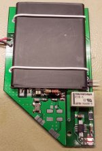
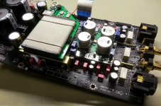
This is how it looks like my mod (mechanically) in place... No electrical connections yet...
The clock board is "floating" on some silicone devices/dampers. The I/V & final board it will be connected directly to the DAC chip, and will provide balanced output too. As all the regulation is made on-board, there is not critical any more the analogue PSU of the player. But good filtering it may be in place actually. I have replaced the original rectifier diodes, with Schottky ones.
I think I will not care too much at this time, but some regulators on original board become obsolete, and may be disabled... to lower even more the heat dissipation.
The clocks board it will be upgraded soon with a common oscillator (divided frequency) for both main processor and DAC chip.
I have tested the QDEO chip with an overclocked frequency (21Mhz), divided from the main DAC oscillator. It were nice to have all the frequencies from only one oscillator... The chip works, but HDMI output is no longer compatible (I suppose is out of standard) with my TV display input. Else I can have picture on another (cheaper) display... Keep searching on this...
Attachments
Last edited:
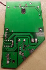
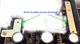
Well, I think I have to come with some clarifications about this mod, and some more informations to those who may be interested to implement it.
Since the pictures of the board it were published here, I come on the need to improve the board, specially adapted for use in Oppo players.
So, there is in production now a improved version (mechanically/electrically).
The new board it will have 3 mount points, which will use some special silicon devices. As one can see in the picture here, there is about two metal mount pieces to be attached to the player, to support this clock board. There is a quite elastic mechanical system. One of this mount is to be soldered directly on the ground plane areas of the stereo board (apply to 105 model). Another mount is to be attached to the player chassis with the help of a spacer (see the picture). More details it may be available if need it.
The last version of the clocks board is designed to accept MMCX connectors. There is a need that the board should be connected after mounting it in place, to the previous soldered in place coax cables. So the MMCX it is a, both elegant and professional solution.
The new board it have implemented access to the Enable pin of the all four oscillators (footprints) provided on board. Also an simple delay circuit (RC) is present on board, in case there is necessary a start up delay of the clock signal in a more demanding power up sequence. For this mod in Oppo player there is no use of these design details provided (the board will not be populated on this option). But in case one may use the board for some other applications, the possibility for more accurate control of the oscillators is there. The board it have also an 5v regulator (not populated, but bypassed for use in 105 player), for the battery charger, in case one may use the board in a system with another available tensions.
There is in production too, a small clock divider PCB, which will fit the two oscillator footprints on the upper side of the clock board.
What is the clue with this divider? Well, in my opinion there is a clue to have a common oscillator/frequency for both main processor in 105 model, and the DAC chip.
As one can see, Oppo designers decided to use an 54Mhz clock for the DAC chip. If one look at this choice, it may think it is stupid to have a so low clock frequency for an ES9018 chip. This chip give much better sound quality performances at higher clock frequencies... My highest frequency for stable use of the DAC chip, is 125Mhz.
As the Oppo designers choice is for the DAC clock frequency, it looks to me to be in close relation with the main processor clock frequency: 54Mhz clock for DAC it is a multiple of the 27Mhz clock frequency which the main processor function with.
My main idea here is to keep this relation between the main clocks in this player, but improve (increase) it. So, why not use a 108Mhz oscillator for DAC chip (it function just exceptional on this frequency), and divide it to get 27 Mhz for the main processor. Well, one can also divide 54Mhz to get 27Mhz. So there is up to everyone to use this principle as one want. My recommendation is to use 108Mhz. And I will use a SAW oscillator.
So, my divider board can divide by 2, by 4, or by 8 (seting up by soldering together some pads on that board). The divider board will be soldered on the clock board as a option. Then it will use the MMCX interface further to the player. More details will come later, together with pictures.
The clock powered board and the divider will be available soon to those interested to use it.
The clock board will be sold without battery and oscillator. The divider, it may be also sold without oscillator, as one may want to use his own. But my recommendation for the divider board is to be fully populated and shielded/soldered on the clock board, for the frequency chosen by user.
It will be also possible (as an option) that these boards will be offered completely equipped/mounted (except the battery), ready for use. Of course for another price...
The complete kit of this mod will include the clocks board, with one MMCX pair connectors, the metal mounts and spacer, and the silicon devices. Also will come in the kit, one foot 0,8 mm coax (soldered to the male connector for some bucks more...).
The board and the divider may have also soldered in place a SAW oscillator for the frequency the user want, but the QDEO chip clock it may be another type. The design it offer quite much flexibility, with quite many options for the exactly set up the user may want/order...
The clock board (without oscillator and battery), the metal mounts/spacer, silicon devices, a foot coax cable, and one pair MMCX connectors, will be sold for a basis price of 45$. Further options it may be discussed for different prices.
Attachments
Last edited:
Is this a "mod" or a product that you will be selling?Well, I think I have to come with some clarifications about this mod, and some more informations to those who may be interested to implement it.
Move the thread to commercial sector?
- Home
- Source & Line
- Digital Source
- Oppo's BDP105 - discussions, upgrading, mods...