True. We all have the tendency to react emotionally
I think we are seeing what I call the "YouTube sickness" becoming wide spread. Insults seems to be the new euphemistic blood sport. It's just bad behaviour - didn't their Mothers give them a deserved spank every now and then? Didn't hurt me.
Then again, I have picked up this book "Science as a contact sport". I kid you not.
jan
Read the book called "Merchants of Doubt" - it could be sub-titled the same.
I am a healthy sceptic, but when war is declared on climate scientists by... the tobacco lobby? No, I am not kidding.
Cheers, Joe
It is what you guys were talking about RECENTLY?
Thank you, never thought I would see this.
It certainly answers one question - what happened to the "lost phase" and I see that "EAR" has been paralleled up. This is useful to know. Currently I am paralleling up the "XLR" and "IO" - but now have the option (as I suspected) to disable the headphone I/V and get back to the four phases the Oppo 95 had. It may be that in my post-DAC implementation (no opamps or "virtual earth") zero feedback, I have that option back with beneficial results.
If Oppo is looking for ways to try an improvement that will be low cost manufacturing wise, replace that 54MHz +3.3V driven oscillator, with something in the region of 50-100MHz SAW oscillator. To my eye they have upped the quality of that +3.3V, so just change a single part, the Sabre DAC oscillator - I bet that a manufacturer can get these as a "one buck" part in QTY. I have a manufacturing background, so have an idea what the added cost would be, here hardly any.
I would put that one on my top-of-the-list improvement for those who want a stock player.
Then - as another suggestion - do the same for the 27MHz Master Clock. But as that is using a stock crystal, then this is a little more complex as you again need a decent +3.3V - also 27MHz SAW could be difficult to source (but maybe not impossible to get manufactured) - or else use 54MHz/2 solution.
Next generation of Sabre DAC fitted Oppo players - this can be achieved at very reasonable cost - near no additional cost.
Cheers, Joe
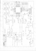
It is what you guys were talking about RECENTLY? I have donated a schematic to make things clearer for everyone. Coris, we are not 'fools' yet we can learn from others.
One of my all-time favourite saying was by Niels Bohr (Eistein's friend and prime sparing partner) who was asked: "Professor, what is an expert?" A thoughtful Bohr took a second and answered: "An expert is somebody who has made every mistake in a narrow field."
AC filter almost burning, why ?
Dear all,
I tried to replace the AC socket by an old (but unused) schaffner filter (fn 323-6/05).
I left the house with the modified oppo in sleep mode, but, after 3 hours, my daugther gives me a call "Dad, it smells terrible in the house, like burned plastic". It was the filter.
Stand by mode consuption is 0.5W ... So I don't really understand what is happening. Is the switching mode supply throwing such a high level of noise ? Can someone gives an explanation ? Doesn't it means that a filter that will stand the power is a must ?
Best regards.
Philippe
PS thank you John for the shematic, btw does someone know where comes the 104 and 474 short cuts for 100 nf and 470 nf respectively ?
.................................................
Coris, we are not 'fools' yet we can learn from others.
Fully agree! I never stated the opposite...
")
.......................................................................
Then - as another suggestion - do the same for the 27MHz Master Clock. But as that is using a stock crystal, then this is a little more complex as you again need a decent +3.3V - also 27MHz SAW could be difficult to source (but maybe not impossible to get manufactured) - or else use 54MHz/2 solution.
Next generation of Sabre DAC fitted Oppo players - this can be achieved at very reasonable cost - near no additional cost.
Cheers, Joe
One main 108Mhz (cheap but very good SAW) clock for DACs as it is, then (4) divided for processor is the reasonable/reliable solution. Differential transport is also a very good and efficient way to be done. The clock distribution chip (added jitter 300fs) is just waiting to be used...
It still yet to find a solution to use the same main clock for the QDEO chip (working on it), and a low cost, high quality, synchronized clocking for the whole system is in place...
Last edited:
Thank you, never thought I would see this.
It certainly answers one question - what happened to the "lost phase" and I see that "EAR" has been paralleled up. This is useful to know. Currently I am paralleling up the "XLR" and "IO" - but now have the option (as I suspected) to disable the headphone I/V and get back to the four phases the Oppo 95 had. It may be that in my post-DAC implementation (no opamps or "virtual earth") zero feedback, I have that option back with beneficial results.
.........................................................................................................
Cheers, Joe
About used of two ways for EAR it is stated quite long time ago by Oppo itself when answering questions about DAC outputs setup in 105 model...
My opinion is that Headphone output is useful and it may be in place, even it take two of DAC outputs. But it may be also a customized solution if one do not want/need EAR out anymore...
About used of two ways for EAR it is stated quite long time ago by Oppo itself when answering questions about DAC outputs setup in 105 model...
I remembered that differently, that two to the XLRs were a pair, then found later not so. So I was wrong and now cleared up that it was EAR.
My opinion is that Headphone output is useful and it may be in place, even it take two of DAC outputs. But it may be also a customized solution if one do not want/need EAR out anymore...
Pretty much my thoughts too. In my upgrade for clients I have been able to say that nothing has been disabled and that 100% functionality guaranteed. So I am loathe to change that policy. But I may try it at some stage. I am delighted with the results of I am getting from the remaining pair (which I do manually).
Cheers, Joe
John Curl,
Thank you very much for the schematic. It will help our discussions.
So using the schematic, we can say that resistors R34, R101, R30, R33 should all have the same value, for example 866 ohms, 1%. This will allow the two differential outputs to be subtracted properly, and the noise canceled properly out of the DAC.
Eric
Last edited:
IOUTRP, IOUTLP it have 1,2K (R33,R101) on I/V feedback.
IOUTRN, IOUTLN it have 0,53K (R34,R30) on I/V feedback.
I (current) OUT (DAC output) R/L (right/left), P/N (positive/negative phases of differential out).
The positive side of the differential signal is out of I/V converter 2 times bigger level than the negative one on both channels of only stereo stage. Not headphone out, no multichannels out. Just this stereo one. How it may be subtracted the two differential outputs in this setup? How the noise it will be canceled properly this way? The main reason of using differential is actually noise canceling. Isn't it?
I still not see the clue/benefit of such process of the DAC differential out in stereo I/V stage. And what for only stereo?
Waiting for more ideas about why this chosen way.
Last edited:
- Home
- Source & Line
- Digital Source
- Oppo's BDP105 - discussions, upgrading, mods...