I'm putting together three different Broskie "Unbalancers" and one of them will most likely use the 6n2p.
When trying to learn the magic of tube curves 😱 I found some "rules of thumb" as we say in Sweden.
Ra should be at least 3 x Ri at the operating point.
Voltage drop at 1/2 to 2/3 of B+.
Distortion low and decreasing (not all H3).
Stay out of the "banana area".
The 6n2p is quite simular to ecc83/12ax7 and usually a plate resistance
around 120k is recomended. Reading Wiki they clame that it could be up to
220k for "hifi use".
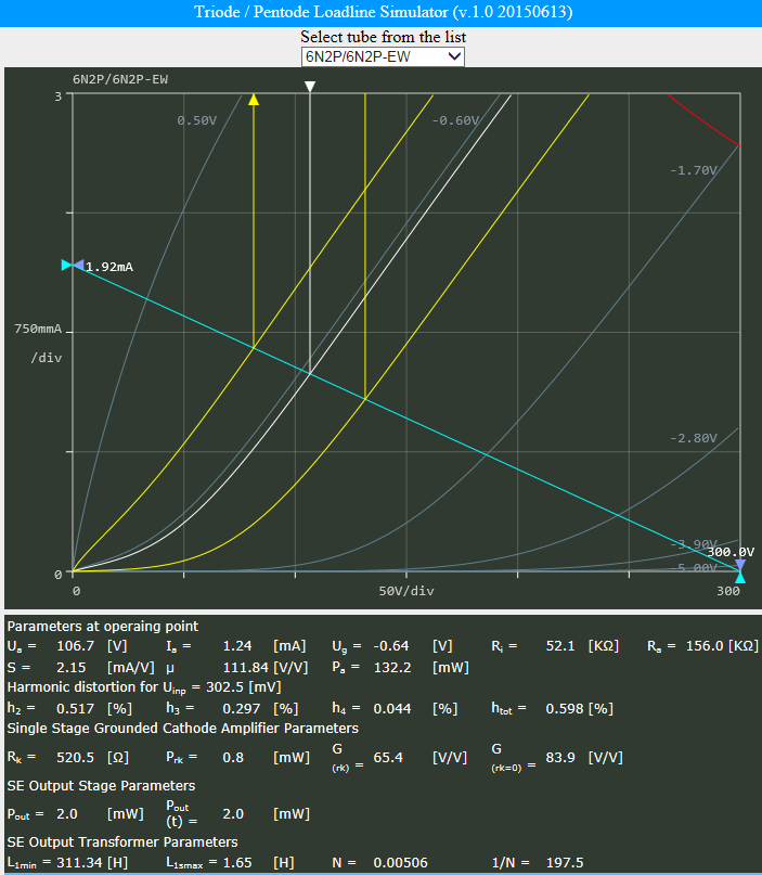
So I was fiddling around with the:
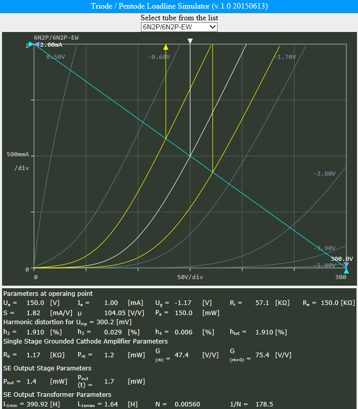
Triode / Pentode Loadline Simulator v.1.0 (20150613 [url]www.trioda.com)[/url]
and came up with this, following the simple rules I mentioned earlier.
If I'm way of on this could someone please explain how and why.
The plate resistance (Ra) at 156k seems higher then most recomendations I have seen elsewhere so........?
When trying to learn the magic of tube curves 😱 I found some "rules of thumb" as we say in Sweden.
Ra should be at least 3 x Ri at the operating point.
Voltage drop at 1/2 to 2/3 of B+.
Distortion low and decreasing (not all H3).
Stay out of the "banana area".
The 6n2p is quite simular to ecc83/12ax7 and usually a plate resistance
around 120k is recomended. Reading Wiki they clame that it could be up to
220k for "hifi use".
So I was fiddling around with the:
Triode / Pentode Loadline Simulator v.1.0 (20150613 [url]www.trioda.com)[/url]
and came up with this, following the simple rules I mentioned earlier.
If I'm way of on this could someone please explain how and why.
The plate resistance (Ra) at 156k seems higher then most recomendations I have seen elsewhere so........?
I've seen 12AX7 grounded cathode circuits featuring a 150k plate resistor. They were biased for around 1mA with a 300V supply. So, I don't suppose that a 156k plate load on a 6N2P would necessarily be out of line, assuming a similar bias current and supply voltage.
Hi,
What are you going to use this for? You have a grid bias voltage of -0.64 volts, and that is rather unusual.Your input (signal) voltage is 302mV it is unusually low for a hifi amp.
What are you going to use this for? You have a grid bias voltage of -0.64 volts, and that is rather unusual.Your input (signal) voltage is 302mV it is unusually low for a hifi amp.
Hi,
What are you going to use this for? You have a grid bias voltage of -0.64 volts, and that is rather unusual.Your input (signal) voltage is 302mV it is unusually low for a hifi amp.
It will be used as the LP output buffer in a 3-way dsp filter, following a Buffalo III dac,
so it's also for I/V converting. I need more gain in that area to get more digital
headroom in the dsp since the subwoofers are dipoles.
I'm using hardwired "Unbalancers" for midbass and ribbons today with 6n6p / 6n30p
and I will keep them almost as they where after building the new pcb ones.
I have chosen the 300mV level to get a fixed level between different simulations, for comparison purposes.
The output tube will most likely be 6N30p.
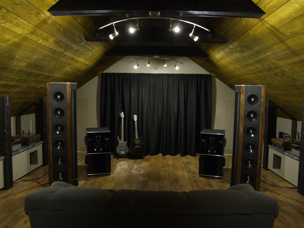
Speakers:
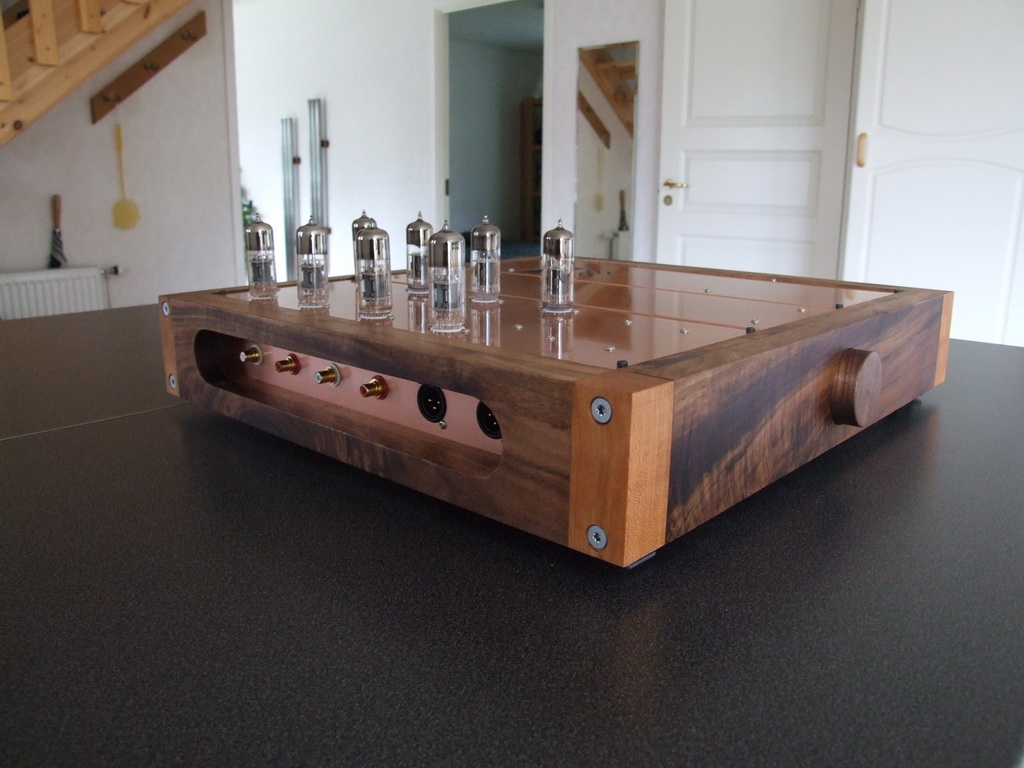
Present dsp:
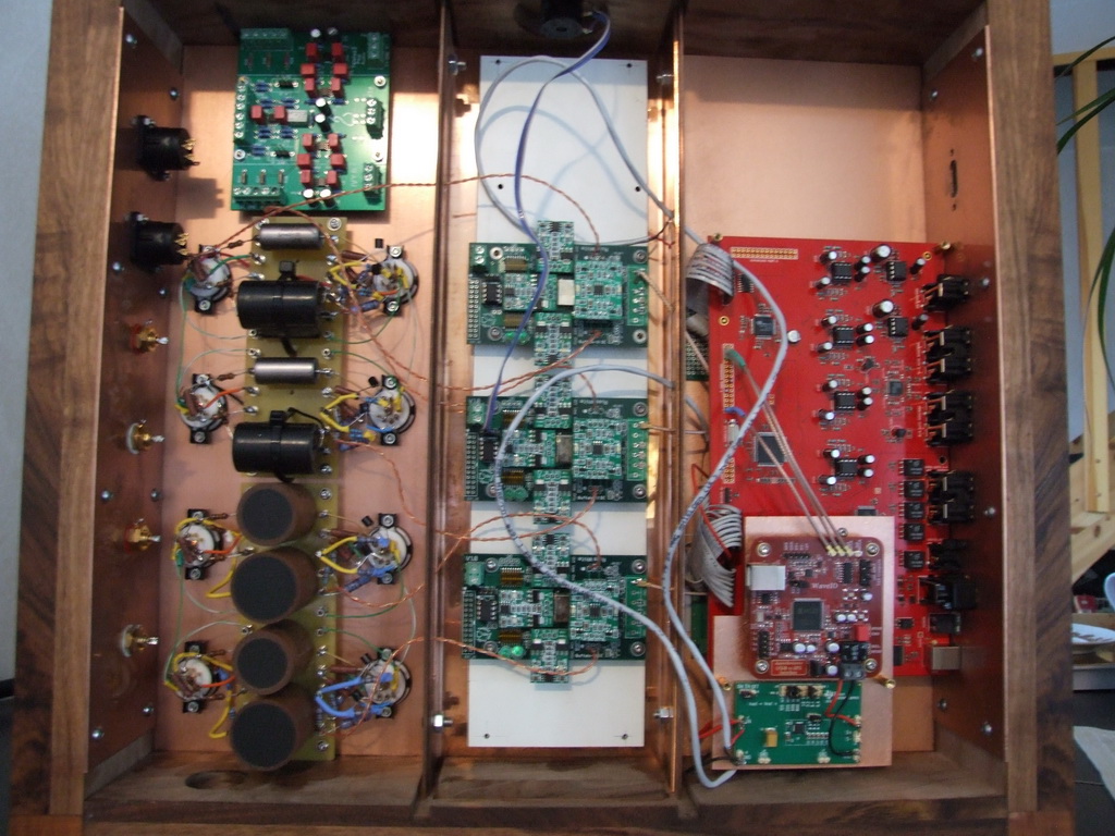
Inside:
Thanks, it's gonna be even better 😎
When looking at the data sheet you can se grid voltage -1,5.
Is this a value that you are supposed to aim for to get the most out of the tube ? I have went from 0,64v to 1,17v is that close enough or ?
When looking at the data sheet you can se grid voltage -1,5.
Is this a value that you are supposed to aim for to get the most out of the tube ? I have went from 0,64v to 1,17v is that close enough or ?
- Status
- Not open for further replies.
- Home
- Amplifiers
- Tubes / Valves
- Operating points for 6n2p