Hi Borge,
If the new parts you are adding to AB1.2 has an interrupt pin, you can tie it to any spare gpio pin, as the AVR32 chip can configure any gpio pin as interrupt pins.
If you intend to add an optical rotary encoder function, you can use the existing ROTI and ROTQ pins used by the sdr-widget.
Adding a graphical LCD will be much more disruptive. Perhaps the existing character LCD 4x20 will suffice.
Alex
With a requirement as flexible as that, you could run from Vusb (4.01-5.25V). I suppose a nice passive filter might help. You would still have rail-to-rail voltage concerns with any voltage level, assuming op-amp buffers for the output drive.Quoting page 38 of the CS8406 data sheet: "The AES3 and IEC60958-4 specifications call for a balanced output drive of 2-7V peak-to-peak into a 110 Ω ±20% load with no cable attached."
I'm assuming that pushing a nominal 5Vpp signal would work with longer cables than 3.3Vpp.
I built my 8406 demo break-out but it does not work (yet) in hardware mode. I'm still debugging.
while searching for clues, I found this link that suggests the 8406 is not the best choice in spdif transmitter chips:
http://www.diyaudio.com/forums/digital-line-level/195117-cs8406-spi-problem-2.html
I don't know the full context. anyone have any experience *using* this chip?
while searching for clues, I found this link that suggests the 8406 is not the best choice in spdif transmitter chips:
http://www.diyaudio.com/forums/digital-line-level/195117-cs8406-spi-problem-2.html
I don't know the full context. anyone have any experience *using* this chip?
can anyone check my use of hardware mode pins:
h/s (24): high (hardware mode)
sfmt0 (4): high
sfmt1 (5): low
apms (10): low (slave mode)
hwclk0 (20): 0 (default 256fs?)
hwclk1 (27): 0 (default 256fs?)
tcbld (11): not sure about this one
tcbl (15): not sure about this one either
cen (16): low (mode A)
v (17): high
u (18): low
copy/c (1): 0 (scms=00 ?)
~emph (3): high (off)
~audio (19): low (is this right?)
orig (28): 0 (scms=00 ?)
test 2,7,8: all high
then I take the lrclock, bitclock and data from the SoC board and I take the master clock from the DAC board area (j7 I think).
not getting any spdif lock on my dac from this setup. I'm sure I've gotton some pins wrong. anyone see any obvious mistakes?
Here is a draft for an ES9012 layout for the AB-1.12 prototyping board. This is a for you die-hard analog hackers out there because PSU and IVC are not implemented but on headers.
All headers are 2.54mm/100mil and will fit onto one and the same veroboard. This will apply to all headers on the AB-1.12 board except the 2.0mm pitch of the module.
Any comments? On my layout green is top and red is bottom. Yellow is the combination of both. My general layout philosophy, as you can see, is to have very low return current impedance with a continuous ground plane under the chip on the top side.
Børge
Hi Alex,
I'll be adding software bit-banging HDMI to it) Thanks for the info!
Actually, I'm sitting here at the airport killing time by drafting an ES9012 layout.
Børge
Attachments
I still can't get the cirrus transmitter to work; but I did get the wolfson version (8804). works good, now that I have it set to slave mode and set the input to be i2s.
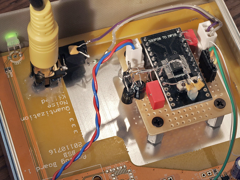

output is to a pulse transformer via a .1 blocking cap. yes, I glued the output rca connector over the 'cat' (lol).
output is to a pulse transformer via a .1 blocking cap. yes, I glued the output rca connector over the 'cat' (lol).
Software control of the digital transmitter-
Check page 17 of this document http://www.asahi-kasei.co.jp/akm/en/product/ak4103a/ak4103a_f01e.pdf to understand why the header info is usually ignored by DAC's. The pro format is completely different from the consumer format for sample rate. Otherwise they both work and all the receiver chips I know of today will ignore the data and lock just fine whether AES or SPDIF.
Check page 17 of this document http://www.asahi-kasei.co.jp/akm/en/product/ak4103a/ak4103a_f01e.pdf to understand why the header info is usually ignored by DAC's. The pro format is completely different from the consumer format for sample rate. Otherwise they both work and all the receiver chips I know of today will ignore the data and lock just fine whether AES or SPDIF.
@ borges, will it be possible to just buy the dac board? how are the registers set? pcm input is not enabled by default on the es9012. i do wonder though, is it wise to have even the high speed pins like the mck input with ground plane top and bottom? would it not be better to erode it from around such pins to avoid the capacitance? you know better than me, its just a thought.
you can pretty much put me down for one though, if i can buy it by itself and have it function, it would be added to another 2 x ackodac 9012 dacs to add another 2 channels in a smaller package for the subs, i already have multichannel usb input, but i might grab yours for playing around with too.
you can pretty much put me down for one though, if i can buy it by itself and have it function, it would be added to another 2 x ackodac 9012 dacs to add another 2 channels in a smaller package for the subs, i already have multichannel usb input, but i might grab yours for playing around with too.
Hi Qusp,
I'll be selling the board stand-alone. It is designed to work with the USB-I2S module, but by all means connect it to whatever you want!
There are quite a few religious movements when it comes to ground layout. I belong to the Henry Ott school with strong focus on return current. See MixedSignalLayout
I know there are other ways out there (like small coaxes etc) but this philosophy has served me well this far. Personally, I worry less about stray capacitance in the present layout than I would about stray inductance in a layout without the ground plane.
Børge
Last edited:
Hi Qusp,
I'll be selling the board stand-alone. It is designed to work with the USB-I2S module, but by all means connect it to whatever you want!
There are quite a few religious movements when it comes to ground layout. I belong to the Henry Ott school with strong focus on return current. See MixedSignalLayout
I know there are other ways out there (like small coaxes etc) but this philosophy has served me well this far. Personally, I worry less about stray capacitance in the present layout than I would about stray inductance in a layout without the ground plane.
Børge
oh i'm not suggesting getting rid of the ground plane entirely as i totally agree with having the best low impedance return current path, this is of particular importance with the es901X dacs AVCC return, just perhaps eroding it from around/under the very high frequency input and output pins, which is a technique i see used quite a lot in mixed signal, RF analogue and particularly usb->i2s and dac layouts. thats great about the board, i'll keep an eye on this thread.
Last edited:
I finally (sort of) got the hardware mode working on the cirrus chip.
I still stand by my feeling about this chip; its fussy and difficult to deal with ;(
its spdif output is strange; I have not scoped it yet but things seem to have a hard time locking onto it. on my behringer stack (dcx/deq2496) the deq seems to lock on but it won't pass data reliably up to the dcx! those 2 are linked by aes/xlr cables and it does not seem to matter if I select spdif or aes. I get a few seconds of music, then muting, then music, then muting. the music sounds ok (not distorted) but it cuts in and out. I am guessing its a level problem on spdif transmit and when I tried different output options (resistor dividers, pulse trafos, even toslink) things are just not reliable. I can get lock in some configs, on another cs chip (8416 inside a gamma1 AMB dac). but on my behringers, they don't want to ever stay locked.
I remove the board with the CS chip and replace with wolfson, same everything else. and locks always happens.
it could be my wiring or still some pins I didn't set right, but I was able to get a continuous stream for one physical config of output spdif on the gamma1, so I know the i2s and power are ok to the CS board.
I still would strongly recommend you go with the wolfson chip. it sure seems less trouble. I know that the CS chips 'do work' as they are used a lot in industry but I've having the devil of a time getting it to interoperate reliably.
btw, the one pin I had to define was TCBLD (set to output). I think i also tried setting validity (V bit) to ground instead of vcc. I don't think I got these wrong as, again, I was able to get music working for at least one physical config while sending to an 8416 receiver based dac.
I found some code, online, that drives the 8805. the 8804 should be nearly the same.
I'm not sure you need to go all software on the chip (lol) when hardware mode is actually more foolproof (better 176k support in hardware mode, I think, since its automatic) but if you need software, I have a link to the C source. not tested and when I emailed the author, I got no support, so it may not even work.
as for the xtal vs clock, I'm not sure I know enough to suggest one vs the other. I've seen both and from what I've read, the xtal solution is preferred by wolfson over an oscillator. the osc will need yet another filtered psu or it can jitter the device; whereas the xtal, on its own, needs no filtering or power supply of its own. maybe the pcb can be made so that either a xtal or oscillator box would fit into the holes (?)
ha! did not even realize it was so easy
WM8804 Linux support released | Open Source at Wolfson Microelectronics
if you google around, there is kernel source for this chip! by wolfson.
I still think its far too much effort to software-drive this chip. its a hardware function and it does one thing. I'm not convinced that adding software when its not strictly needed is complexity that justifies itself; but if you NEED to be software based, I suppose this is a good starting point.
I had a quick read thru the source and it looks like a nicely done job; and of course, authoritative. and GPL, too, which is kind of nice.
WM8804 availability is so-so. I checked at OEMsTrade - Electronics Part Search. Farnell have 1k, that's about it.
Børge
Børge
also, the 8805 is equivalent, if not overkill. I have not tried using it for i2s input as its mostly a multi-in, single spdif or single i2s output chip; but I'll see if that one also does i2s->spdif.
it has more pins, but in some places (newark) they are cheaper! $2 each on sale.
wonder if we could get lucky and if they are pin for pin, if you want to treat the 8805 as just a 8804? checking the data sheets, the lower pins are almost all 1:1. its the upper section (near pin1 area) that the pins vary.
it might be odd, but I think it would be possible to make the footprint for the chip large enough to handle the 8805 but meant for the 8804. some jumpers would be set to change the 1 or 2 pins that are a bit differently located and route them to the equiv tie points. I bet it could be done and that way you'd have a choice of either of the 2 chips.
you would want to keep these both in hardware mode, though. I think it would be easier that way (?)
if farnell has 1000 in europe and mouser has about 900 here, do we NEED to have more onhand? this chip is not being discontinued and it seems popular enough that it should not go out of supply any time soon. of course its worth giving wolfson or a distributor a call if you need to lock in a certain amount of quantity.
As far as what I understood about the WM8804 so far, it will have better jitter rejection if the OSCCLK is synchronous with the input word clock. This is only possible in software mode, unfortunately. With hardware mode you have to take 12 MHz, which is always asynchronous.I found some code, online, that drives the 8805. the 8804 should be nearly the same.
I'm not sure you need to go all software on the chip (lol) when hardware mode is actually more foolproof (better 176k support in hardware mode, I think, since its automatic) ............
Also, I'd suggest to provide a possibility to fit a clock with dedicated low noise regulator. Demian posted one elsewhere, suitable for a clock. And no need for fancy clocks, but preferably those with specified phase noise down to an Offset of 10Hz or less, which is important for audio.
- Home
- Source & Line
- Digital Source
- Open-source USB interface: Audio Widget