that's why I insist that there should be two different branches of the project: one with focus on portable use and another one with focus on SQ, for home use only.The ideal is with a constant current source. But starting from 5 V. going to be impossible.
IMHO the portable version(s) should be something like the current designs, particularly George's ones: as good as possible while being small, cheap and "USB power-able" (that is, USB powered with a connector for optional external 5V supply which cuts USB power when plugged in).
I'd make it single board, perhaps with the DAC chip itself (plus a minimal number of components, such as small local by-pass) mounted on a tiny "piggy-back" board to allow for the possibility to "swap in" different suitable DACs such as the ES9023, PCM5102, etc.
The home version(s) must be mains powered. Forget about 5V and single supply, go for as many and as high as convenient supply rails. They should be modular, too. I would split it into several boards as follows:
- main AC PSUs board
- uC board (USB interface)
- galvanic isolation board
- DAC board
- digital output(s) board
- other options board(s)
The interface between 2. and 3 as well as 3. to 4. or 5. should be identical, so that the galvanic isolation board becomes optional: it may be omitted by directly connecting uC and DAC boards or added (even in a second time) just by inserting it in between the two (like in a daisy chain).
The DAC and digital output boards must host the clocks (and clock "switch", etc). Economically it would be more convenient to put the clocks and related circuitry on the uC board (or on the galvanic isolation board), but for best performance (minimum jitter) the clock must be as close to the DAC chip as possible.
Perhaps, also the digital output and DAC boards may be made daisy-chain-able, so that a user may setup a device with both analog and digital outputs.
It would be nice if the uC board might also have connectors for optional input board(s), either digital (S/PDIF, I2S), analog (ADC) or both.
The whole design of the "home branch" should be "future-proof": if you will eventually replace the uC for another one allowing for up to 384KHz/32bit, it must be possible to swap-in the new uC board without changes. And it should also be possible to exploit the new capabilities with no or minimal changes to the other boards.
Last edited:
I can see desire to mix and match with the full size unit where you may want to experiment with PS, capacitor selection etc but there is limited opportunity to experiment with my boards.
I have no problem reworking my design into a 2 part system but I don't see many takers when you will be offering the full buffet of choices with the 'home version'.
George
I have no problem reworking my design into a 2 part system but I don't see many takers when you will be offering the full buffet of choices with the 'home version'.
George
The whole design of the "home branch" should be "future-proof": if you will eventually replace the uC for another one allowing for up to 384KHz/32bit, it must be possible to swap-in the new uC board without changes. And it should also be possible to exploit the new capabilities with no or minimal changes to the other boards.
I thought Alex already demonstrated 384Khz/32bit transfers through the existing micro, and were waiting for George's 5102 board to verify 32 capability end to end?
I thought Alex already demonstrated 384Khz/32bit transfers through the existing micro, and were waiting for George's 5102 board to verify 32 capability end to end?
I believe it was 32/192...
Brgds
I agree with UnixMan's approach too, but at the same time I would like to see "core modules" that could work on their own and then other modules could be added to upgrade performance as the user sees fit. So, lets say the USB and DAC boards were the core and could operate by themselves (possibly powered by USB), and then the more advanced power supplies, etc could be added as the owner upgrades.. (thinking about playing with that idea myself when I have some free bandwidth.)
Last edited:
Each separate board adds to the minimum cost of the total solution. It's certainly possible to make boards fairly cheaply, but there is separate overhead for each one and that needlessly adds cost. My preference is a single board which has everything necessary; with sections that can be left blank if the features are not desired and/or connectors that can be used to bypass parts of the basic design for upgrades. In the latter case, stacking connectors can allow multiple outputs, even combined with the default, on-board outputs.
Keep in mind that a single board can have divided power planes just as if there were two or more separate boards, making it pointless to actually build two or more PCBs just for isolation.
I certainly see that it may seem strange for me to complain about price on what hopes to be audiophile quality sound, but it's just too easy to get up to $500, $1,000 or $2,000 just for the populated boards and basic case. I'd rather see the bulk of the money going into high-grade DAC chips rather than just having a pile of boards.
Each separate board adds to the minimum cost of the total solution. It's certainly possible to make boards fairly cheaply, but there is separate overhead for each one and that needlessly adds cost. My preference is a single board which has everything necessary; with sections that can be left blank if the features are not desired and/or connectors that can be used to bypass parts of the basic design for upgrades. In the latter case, stacking connectors can allow multiple outputs, even combined with the default, on-board outputs.
Keep in mind that a single board can have divided power planes just as if there were two or more separate boards, making it pointless to actually build two or more PCBs just for isolation.
I certainly see that it may seem strange for me to complain about price on what hopes to be audiophile quality sound, but it's just too easy to get up to $500, $1,000 or $2,000 just for the populated boards and basic case. I'd rather see the bulk of the money going into high-grade DAC chips rather than just having a pile of boards.
But a single board is restrained to grow in 2 dimensions. Multiple boards can be stacked to keep a small footprint.
Brgds
Very true. As I mentioned, the daisy chaining for multiple outputs could be implemented by stacking headers.But a single board is restrained to grow in 2 dimensions. Multiple boards can be stacked to keep a small footprint.
However, when the primary motivation for all of this separation is to isolate the various building blocks, stacking introduces the very real possibility of electromagnetic interference from one board to the one above or below. In other words, if you take expensive measures to isolate your DAC from the USB, but then stack the analog section of the DAC board directly above the noisiest USB traces - well, then you've got a whole new problem that is an order of magnitude more difficult to plan for compare to traditional 2D board layout.
In general, compact electronics are not always the highest performance.
Demian and Oneoclock,
I will add your PSU to the AB-1.12 prototype board. This will be an unassembled board compatible with form factor and module from AB-1.1.
Before I can start with the layout I have a couple questions:
- Can you suggest an SMD version of the diode?
- Are you okay with 350mW SOT23 MMBT4403 and MMBT3905?
- Should eash XO have its own regulator, or share one?
- Should DAC also have a regulator like this?
Børge
I tested a modified source for the 3.3 vol. analog AB1.1.
An externally hosted image should be here but it was not working when we last tested it.
I checked with an oscilloscope, in every moment only works one regulator and the other is disable. May be worth the same power supply for two clock.
I had at home 100 uF. But regarding simulations, the analog circuit can have a value from 25 uF or higher.
Yes for me SMD diode or what's easiest.
I had at home 100 uF. But regarding simulations, the analog circuit can have a value from 25 uF or higher.
Yes for me SMD diode or what's easiest.
Would we benefit from a small resitor betweed the junction of R10 and the junction of C9 to AVCC - 2ohms or something?
Just a feeling to have semis without filtering right out...
Brgds
That would raise the source impedance at DC significantly. If the circuit is stable there is no downside to directly connecting it to the load.
That would raise the source impedance at DC significantly. If the circuit is stable there is no downside to directly connecting it to the load.
Yes I agree Demian but if it isn't there is a big chance off oscillation. Does the fed circuits draw the same current whatever happens in the audiostream? What I see is that the circuit is expected to dance along in a predicted realtime manner with the load which is changing fast. A way to calm it down and not follow the load (woman) in every point in time is to give her a bit of resistance...
Brgds
Demian and Oneoclock,
I will add your PSU to the AB-1.12 prototype board. This will be an unassembled board compatible with form factor and module from AB-1.1.
Before I can start with the layout I have a couple questions:
- Can you suggest an SMD version of the diode?
- Are you okay with 350mW SOT23 MMBT4403 and MMBT3905?
- Should eash XO have its own regulator, or share one?
- Should DAC also have a regulator like this?
Børge
Lets look at the clocking as a critical subsystem. You have two oscillators with an enable that switches between them, a divide by 2 for the micro and the need to send really clean clocking to the DAC. The frequencies of the oscillators are high enough that they can be isolated with a ferrite bead and a .1 cap to probably 60 dB on the power supply.
I would, space and budget permitting, use a single regulator with isolation resistors on both supply and ground for the oscillators, the flip-flop and possibly an output buffer for the clock signals. I would transformer couple the outputs so ground related noise doesn't get into the oscillator system or cause modulation at the DAC input. Transformer isolation on the clock back to the USB subsystem will keep its noise away from the clock system as well.
Using another regulator on the output DAC brings up the question of supply requirements for the DAC. The ES9023 needs a single 3.3V supply. The PCM 5102 needs two separate supplies and a separate regulator for each makes sense.
Neither have much output drive and I think a headphone amp would enhance the usability enormously, making this an equivalent to a Proton with 192KHz support. I would suggest the TI TPA6130A2. There are others but most are harder to get and not better. The TI does need control to function. The TI has a differential input allowing good noise isolation if used carefully. It also has its own charge pump. It does not need a regulator and can run from the 5V supply.
Yes I agree Demian but if it isn't there is a big chance off oscillation. Does the fed circuits draw the same current whatever happens in the audiostream? What I see is that the circuit is expected to dance along in a predicted realtime manner with the load which is changing fast. A way to calm it down and not follow the load (woman) in every point in time is to give her a bit of resistance...
Brgds
Supplying power to an oscillator is like powering a resistor. The dynamics of the load are infintessimal if its working right. Powering a DAC has dynamics and that is where stability is critical. Most regulator circuits do connect the pass transistor directly to the load. Making it stable is not too difficult and with decent spice software its pretty easy to get close on the first pass. But you are right to ask the question and it should be bread-boarded and tested thoroughly.
Feature creep
Modularizing the system (I think I mentioned this earlier as well) and adding other capabilities is really interesting, and a good way to never finish even a part of the project. Constraints are a really good way to focus and really optimize a specific system for a specific task.
Taking the USB interface and mixing it with a premium DAC + SPDIF/AES interface is a different set of problems and also very interesting. If this SPDIF interface http://www.diyaudio.com/forums/digital-line-level/192465-asynchronous-i2s-fifo-project-ultimate-weapon-fight-jitter-25.html can be "integrated' functionally with the USB interface it would be a pretty comprehensive input but a completely different project. if that is of interest the pieces are all here. They just need to be pulled together and someone needs to run with it. its very possible to add pieces and tweak to get tot he level of a Meitner or a Berkeley Audio with the project components on DIY. The work on this and on the fifo are as good as anything I have seen anywhere, better than most. The software quality is also very good.
Very interesting consideration, but I would say SPDIF input and USB input are fundamentally different, and should not be combined in a minimalist project. SDPIF is a push clock system requiring reclocking at the output. USB is ideally a pull clock system that can more easily run with the DAC as the master. I'd say that adding SPDIF input would be a huge change, and I personally recommend against it unless you actually want to build a monster.Taking the USB interface and mixing it with a premium DAC + SPDIF/AES interface is a different set of problems and also very interesting. If this SPDIF interface Asynchronous I2S FIFO project, an ultimate weapon to fight the jitter can be "integrated' functionally with the USB interface it would be a pretty comprehensive input but a completely different project.
Edit: SPDIF doesn't necessarily require reclocking, but some mechanism must exist to account for the competing clocks. That means either a PLL to match the input clock or reclocking to match the data to the output rate. Either way, SPDIF requires a complex block that is not needed for USB. It's much more involved than simply adding minor electronics for the input jack. On the other hand, SPDIF output in parallel with the I2S output might be simple, but that might as well be treated the same as adding a different DAC.
Last edited:
if anyone's interested, I just got a pcm5102 DAC going, fed from the audio widget's i2s lines. forgive the 'informal construction' (lol):
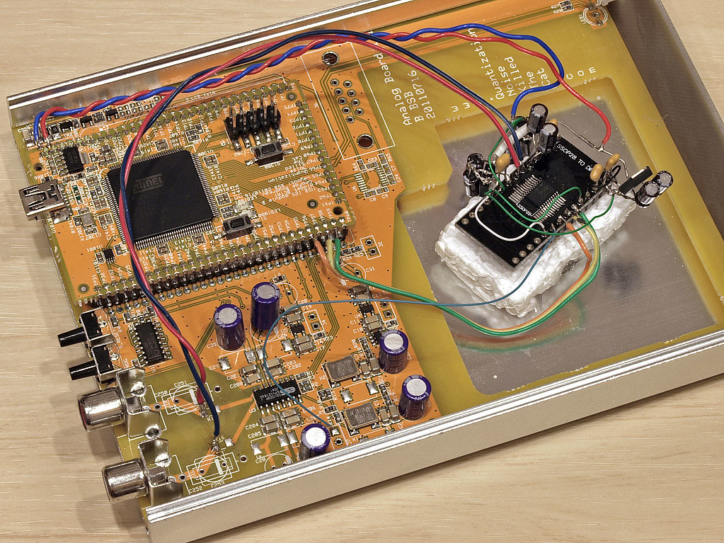
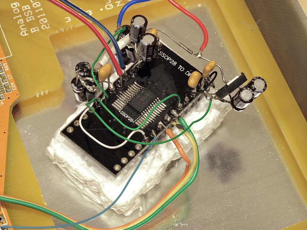
I wanted an easy i2s source and this sure provided one for me")
the ESS is offline (removed the 0R series R's on the pcb) and I'll listen to the TI dac for a while. like the ESS, its direct-out, internal charge-pump and very low cost/component count. I used all the bypasses the spec sheet said to use, which is why so many things are hanging off the chip-carrier
fwiw..
I wanted an easy i2s source and this sure provided one for me
the ESS is offline (removed the 0R series R's on the pcb) and I'll listen to the TI dac for a while. like the ESS, its direct-out, internal charge-pump and very low cost/component count. I used all the bypasses the spec sheet said to use, which is why so many things are hanging off the chip-carrier
fwiw..
- Home
- Source & Line
- Digital Source
- Open-source USB interface: Audio Widget