EDIT: Upon rereading this, I guess maybe you're saying that the advantage is the 64-bit aspect, not the fixed point aspect. I usually work with a DSP that has 40-bit and 80-bit accumulators, so at first I did not see your point.
Knowing Steph I'd say that his point was that in comparison to the DSP56k which he has experience of, a 64-bit accumulator is an advantage, yes. 32bit coefficients are called for in lower frequency bi-quads such as might be needed for a subwoofer XO in order to maintain adequate noise performance. 32 bit floating point I don't feel would be a very good choice for a crossover filter seeing as its precision is 24bits.
I guess that when you press a general purpose processor into DSP work, you typically have to deal with smaller 32-bit registers, but with special purpose DSP chips you have the advantage that the processor is already designed with enough bits of overhead to handle calculations properly. This suggests to me that a great option would be one of the Texas Instruments chips that combines both an ARM and TMS320 DSP in the same package. Perhaps overkill for a crossover, but certainly the DSP will have appropriate instructions and registers for filters.
ARM Cortex-M supports some instructions that concatenate two registers as far as I'm aware - I've used the (M3) load- and store- double instructions myself. I haven't studied the M4 DSP extensions in detail yet though. The M3, although not designed as a DSP does have a (rather slow) double multiply accumulate.
The AM335x datasheet (doc number SPRS717 –OCTOBER 2011) says "Up to Four Serial Data Pins per McASP". See page 69 : Table 2-53. McASP/MCASP0 Signals Description. They are all laid out. Four data pins per McASP port, that you can individually define as input or output. Same as DSP56K.I have worked with the TI McBSP ports and have studied the McASP ports. I would suggest that the most you could hope for with up to two McASP ports is to implement up to two I2S lanes. If you'd care to explain how a single McASP port can implement two parallel I2S lanes, or even if you can just point to a specific page in the Texas Instruments documentation which gives any clue as to how this could be pulled off, then I would be seriously interested in learning a new technique.
Last edited:
Indeed. When you optimize the way an IIR BiQuad is interfacing the multiplier-accumulator, when you realize that the IIR storages contain truncated data, and when you realize how such truncated data actually gets recirculated and amplified in the two recursive paths, then you realize that the 32*32+64=64 fixed point math delivered by a 5.00 dollar ARM chip is surpassing all 24/56 bits fixed point systems and all 28/56 bits fixed point systems. A 40/80 bits system like SHARC looks better. In theory. What is the storage width in a SHARC ? If the SHARC storage width is only 32-bit, it means that you only can multiply a 32-bit number with a 32-bit number, thus there is no advantage for using a so-called 80-bit SHARC processor for IIR BiQuads. The exact same 32-bit truncated data gets recirculated and amplified in the two recursive paths of your IIR.I guess maybe you're saying that the advantage is the 64-bit aspect, not the fixed point aspect. I usually work with a DSP that has 40-bit and 80-bit accumulators, so at first I did not see your point. I guess that when you press a general purpose processor into DSP work, you typically have to deal with smaller 32-bit registers, but with special purpose DSP chips you have the advantage that the processor is already designed with enough bits of overhead to handle calculations properly. This suggests to me that a great option would be one of the Texas Instruments chips that combines both an ARM and TMS320 DSP in the same package. Perhaps overkill for a crossover, but certainly the DSP will have appropriate instructions and registers for filters.
Try a 2nd order Linkwitz Transform at 45 Hz basing on a IIR BiQuad, using a 96 kHz or 192 kHz sampling frequency. However looking high-end today, it will soon become mainstream. Linkwitz Transforms are known and used in analog technology since decades. They exhibit a -140dB distorsion and noise floor using modern opamps, when operated at a constant line level (meaning that the volume pots need to be located after the crossover). What we want is to get the same performance level from digital, with some added flexibility. The bad news is that all 24/56 bits fixed point systems and all 28/56 bits can't and won't adjust to such requirement. Only the 32*32+64=64 fixed point math delivered by ARM has the required flexibility. And it costs less. And it takes less current. The SHARC looks extremely expensive, and no improvement over ARM because of the same 32 bit storages as the ARM. This is in a IIR context.
Take any "good old" 44.1 kHz and 48 kHz system, present an analog square wave at 1 kHz, digitize it using a decent ADC, store it, and output it back in analog using a decent DAC. What do you get ? A square wave again ? Not at all. What you get back is an ugly wave exhibiting ringing, overshoot, and preshoot.
What did you expect ? A gentle, rounded-edge square wave ? Clearly, personally, what I did expect was a square wave like after getting filtered by a 8th-order lowpass Bessel at 20 kHz. Who delivers this today ?
We are not talking about daddy's DSP like the early 3M or SoundStream digital recording and mastering systems in the early eighties. We are 30 years later, with cleaner and more demanding expectations.
We are not interested in reproducing CDs that have been mastered using daddy's DSP techniques. We want to clarify the whole recording process, mixing process, and mastering process, ensuring that a 1 kHz square wave at the input, shows as a 1 kHz square wave at the output, just before the power amps in case there is no DSP inbetween. This is the aim of 96 kHz and 192 kHz audio DSP. I feel this is a basic, gentle requirement in 2011.
So logically, 96 kHz or 192 kHz for adding DSP looks mandatory. Logically, such 96 kHz or 192 kHz system must execute a Linkwitz Transform as low as 45 Hz with less than -140 dB distorsion and noise floor.
DSP means flexibilituy, so logically, such 96 kHz or 192 kHz system needs to be powerful enough for allowing a high-resolution gain and phase linearization of each transducer individually, thanks to 128-tap or 512-tap FIRs. In a crossover, controlling the phase of the transducer is mandatory. With IIRs you cannot tailor the gain and the phase independently at your will. You get more freedom with a FIR.
This being said, a powerful room equalizer may be desirable at the input, for guaranteeing a 2 dB corridor between 35 Hz and 17 kHz. Such room equalizer would require a 512-tap FIR.
Having realized this, you understand that your next audio DSP chip needs to be clockzed around 400 MHz, and provide a single-cycle 32*32+64=64 fixed point math, with 32 bit storages.
For doing the crossover kernel, you can use any technique, IIR or FIR. With IIRs you can emulate textbook crossovers like a Baekgaard (a state-variable IIR BiQuad delivering the bass, mid and high), a Linkwitz-Riley, a Lipshitz-Vanderkooy delay-compensated, etc ... With a FIR in the crossover kernel, you can emulate textbook crossover (that's not efficient from a computing point), or you can design extremely steep crossovers exhibiting 100dB/octave slopes, and tailor the phase response at your will (that's a new area we should investigate).
Steph
Thanks for the hint. The real meat is in SPRUH73A, where details are given in how the clock signals are shared for each data I/O pin and how separate EDMA channels can be used for the separate I2S streams.The AM335x datasheet (doc number SPRS717 –OCTOBER 2011) says "Up to Four Serial Data Pins per McASP". See page 69 : Table 2-53. McASP/MCASP0 Signals Description. They are all laid out. Four data pins per McASP port, that you can individually define as input or output. Same as DSP56K.
Unfortunately SPRUH73A cannot be downloaded at the moment. Fortunately there is still SPRU041J concerning the TMS320C6000 DSP. Please let us know when SPRUH73A (or a new version) can be downloaded.Thanks for the hint. The real meat is in SPRUH73A, where details are given in how the clock signals are shared for each data I/O pin and how separate EDMA channels can be used for the separate I2S streams.
Update : SPRUH73A is still there, but incorrectly referenced by all AM335x T.I. webpages. Go to http://www.ti.com/ webpage. Enter "SPRUH73A" in the search box. The first seach result is the good one. You can download SPRUH73A from http://www.ti.com/lit/ug/spruh73a/spruh73a.pdf. McASP description to be found on chapter 22 page 4190.
Hope T.I. silicon is less chaotic than their webpages.
Last edited:
Take any "good old" 44.1 kHz and 48 kHz system, present an analog square wave at 1 kHz, digitize it using a decent ADC, store it, and output it back in analog using a decent DAC. What do you get ? A square wave again ? Not at all. What you get back is an ugly wave exhibiting ringing, overshoot, and preshoot.
What did you expect ? A gentle, rounded-edge square wave ? Clearly, personally, what I did expect was a square wave like after getting filtered by a 8th-order lowpass Bessel at 20 kHz. Who delivers this today ?
Steph
The ringing comes from the oversampling filters used in the sigma delta DACS and ADC's. It has got nothing to do with the DSP. If you directly connected a sigma delta ADC to a sigma delta DAC without any intervening processing you would get exactly the same ringing on the square wave
")
Alas, they have so many complex DSP chips that there is quite a bit of chaos. Look on their E2E Forum and Wiki and you'll find some of the strange silicon bugs that I've uncovered. If you actually utilize all of the various peripherals and features then there's a chance you might run into a little chaos. I don't think any other manufacturer of esoteric embedded chips has silicon without errata, though.Hope T.I. silicon is less chaotic than their webpages.
Right. You don't want to see the full picture. Show me an ADC and a DAC combination working at 44.1 kHz or 48 kHz that is delivering the required square wave in / square wave out. Without staircases. Without aliasing. If you can show this, I will revise my opinion, and will consider that daddy's DSP operating at 44.1 kHz or 48 kHz remains a valid foundation.The ringing comes from the oversampling filters used in the sigma delta DACS and ADC's. It has got nothing to do with the DSP. If you directly connected a sigma delta ADC to a sigma delta DAC without any intervening processing you would get exactly the same ringing on the square wave
Indeed I went on the E2E Forum and Wiki. It's quite a mess over there with different kind of people mixing, some having trouble with the booting schemes, others asking how to port Android on the AM335x, and others like you presumably wanting to regain bare metal, hence uncovering bugs.Alas, they have so many complex DSP chips that there is quite a bit of chaos. Look on their E2E Forum and Wiki and you'll find some of the strange silicon bugs that I've uncovered. If you actually utilize all of the various peripherals and features then there's a chance you might run into a little chaos. I don't think any other manufacturer of esoteric embedded chips has silicon without errata, though.
I very much like the AM335x features, but at this stage I get somewhat discouraged, seeing that "more may mean less".
If T.I. could deliver more support software like the one they have regarding the pin configurator, that would be fantastic.
I can't believe that in 2011, more than 30 years with microcontroller, there is no global digital standard describing the registers, some recommended configurations, in an interactive way possibly using XML. You would configure a chip, define the boot sequence, configure the pinout and the peripherals, by loading an XML parser eventually featuring a graphical user interface. This should be incorporated in the software debugger, for generating the associated initialization code.
Right. You don't want to see the full picture. Show me an ADC and a DAC combination working at 44.1 kHz or 48 kHz that is delivering the required square wave in / square wave out.
I do find myself questioning why squarewave performance is relevant to audio. But sure its possible - but only using oversampling.
Run the squarewave into an ADC sampling at say 32X - so the ADC needs to be running at 1.4MHz, not a major problem with today's technology. It wouldn't need to be the full 16bits either because we're reducing the bandwidth. This ADC can have a fairly gentle bessel AAF which does not generate ringing. Then downsample to 44k1 using a minimum phase FIR filter. On the output do this in reverse.
You'll get overshoot and ringing because the bandwidth reduction is severe but you'll avoid staircases and aliasing.
I very much like the AM335x features, but at this stage I get somewhat discouraged, seeing that "more may mean less".
That was indeed my initial response to the datasheet on that part. Its so much more that do I really want to invest the time learning to get the best out of it? Too big an investment of time I feel, so I'm going to stick with the Cortex M for now because it does suit my needs well.
Right. You don't want to see the full picture. Show me an ADC and a DAC combination working at 44.1 kHz or 48 kHz that is delivering the required square wave in / square wave out. Without staircases. Without aliasing. If you can show this, I will revise my opinion, and will consider that daddy's DSP operating at 44.1 kHz or 48 kHz remains a valid foundation.
why operate at 48K ? What not operate at 96KHz or 192K at 24 bit ??
regards
Trev
What I'm suggesting is to run the squarewave into an ADC sampling at 32x - so the ADC needs to be running at 1.536 MHz, not a major problem with today's technology. It wouldn't need to be the full 16 bits either because we're reducing the bandwidth. This ADC would have a 8th order Bessel lowpass AAF -3dB at 34 kHz which does not generate ringing. Then downsample to 192 kHz using a FIR filter emulating a 16th order Bessel lowpass -3dB at 34 kHz. Stay 192 kHz in the storage and audio processing. For the output, use a non oversampling DAC operating at 192 kHz, and analog lowpass the signal using a 8th order Bessel reconstructing lowpass -3dB at 34 kHz. You'll get no overshoot, no preshoot, no ringing, only tiny staircases at -70 dB, that you may eradicate by increasing the order of the DAC reconstructing lowpass.Run the squarewave into an ADC sampling at say 32X - so the ADC needs to be running at 1.4MHz, not a major problem with today's technology. It wouldn't need to be the full 16bits either because we're reducing the bandwidth. This ADC can have a fairly gentle bessel AAF which does not generate ringing. Then downsample to 44k1 using a minimum phase FIR filter. On the output do this in reverse. You'll get overshoot and ringing because the bandwidth reduction is severe but you'll avoid staircases and aliasing.
Now realizing this, an nice improvement would be to define the global filtering function (ADC, FIR, DAC) as a 32nd order Bessel -3dB at 34 kHz, then decompose such function in three segments : 8th order for the DAC, 16th order for the FIR, and 8th order for the DAC. None of the three are Bessel anymore, if taken individually, but what matters is that when taken together, they form a 32nd order Bessel -3dB at 34 kHz.
Last edited:
Now the poor man's version of what got suggested in the above post. Running at 96 kHz instead of 192 kHz and defining the global lowpass function as a 32nd order Bessel -3dB at 17 kHz instead of 34 kHz.
Wondering if a NOS DAC like a TDA1545 could be persuaded to run at 96 kHz. If yes, the suggested poor man's system may deliver some interesting results. May try something recent like T.I. DAC8562 or DAC8563, with a Glitch Energy of only 0.1 nV-s.
Any suggestion for a poor man's ADC comfortably running at 768 kHz, say 14 bit resolution ? T.I. ADS7945 or ADS7946 perhaps ?
Last edited:
Wondering if a NOS DAC like a TDA1545 could be persuaded to run at 96 kHz.
Easy job - the datasheet specs are shown for a sample rate of 192kHz, it will go up to 384k.
Any suggestion for a poor man's ADC comfortably running at 768 kHz, say 14 bit resolution ? T.I. ADS7945 or ADS7946 perhaps ?
ADI has a very nice quick search function for ADCs now, it turned up this one which is the cheapest 14 bit part with enough speed - $5 in volume. THD is -96dB @ 100kHz in. SNR 79dB in 500kHz bandwidth translates to 91dB in 30kHz.
http://www.analog.com/static/imported-files/data_sheets/AD7264.pdf
LPC43XX now 204MHz
Eat your heart out STM, your 'fastest M4' at 168MHz has been easily bested by NXP
NXP boosts LPC43000 to 204MHz, hits the shelves
NXP are saying the bottom of the range asymmetric dual-core M4/M0 part will be under $4 in 10k.
Updated datasheet here: http://www.nxp.com/documents/data_sheet/LPC4350_30_20_10.pdf
Last edited:
As for the software for the DSP manipulations - i'm working on something related to this...
Graphic Filter Designer
The idea is to simulate the analog circuit in digital domain with a PC, and then "compile" it to different targets
- Analog boards
- DSPs
You'll be able to design the filters for DSPs alone, if you use digital-only filters (delays, or non-textbook biquads or whatever else. No FIRs... )
I've got signal chaining, control points, biquad graphing, and a loop of control point>change of parameters of filter>generation of biquad parameters>chaining of different biquads>graphing in a single mouse stroke.
Graphing of FR is ready too
+ FFT with windowing functions.
Windows only...
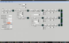
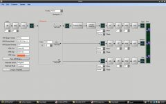
Wonderful ! Would be nice to have a crossover signal flow like the one I've attached. Is it feasible ?I've got signal chaining, control points, biquad graphing, and a loop of control point>change of parameters of filter>generation of biquad parameters>chaining of different biquads>graphing in a single mouse stroke.
Graphing of FR is ready too. Also FFT with windowing functions. Windows only.
Attachments
Last edited:
I had a look to the newest PIC32MX1xx and PIC32MX2xx from Microchip. Their two SPi do now feature an I2S mode for interfacing audio CODECs and DACs.
Quite bizarre is that those new chips now materialize the low-end range of the PIC32 product family. Those new chips only support a 40 MHz clock. Only 2.25 eur from Mouser, dropping to 1.56 eur when in 150 qty. They have revised the Slave_Select pin management of their SPI, enabling it to operate as LRCK for implementing I2S. As slave and as master. There is an explicit MCLK signal, internal. There are now 5 Special Function Registers associated to SPI (beforehand, there were only 4 such registers). SPIxCON2 is the new SPi Special Function Register, dealing with the audio modes (I2S) of the SPi.
Such PIC32MX1xx and PIC32MX2xx can be used as crossover building blocks.
One PIC32MX2 as pre-processor (possibly with USB2 audio input, possibly asynchronous), using one SPi in the I2S mode, and one SPi for controlling the DACs volumes.
Two PIC32MX1 exploiting the same pre-processed signal, acting as crossovers, each outputting two I2S lanes.
You get a stereo 4-channel xover executing 32*32+64=64 math.
Something a Freescale DSP56K or an Analog Devices ADAU1401A can't do.
There would thus be three PIC32 chips on the xover board.
I own a Microchip ICD3 debugger.
Can I program and debug all three chips individually, from a single debug connector ?
Is there something like the ARM "SWD multidrop" debug protocol, in the Microchip world ?
Last edited:
Would this mean an Embedded Artists LPC43xx LPCXpresso Board at 20 eur plus tax ?NXP are saying the bottom of the range asymmetric dual-core M4/M0 part will be under $4 in 10k.
- Status
- This old topic is closed. If you want to reopen this topic, contact a moderator using the "Report Post" button.
- Home
- Source & Line
- Digital Line Level
- Open Source DSP XOs