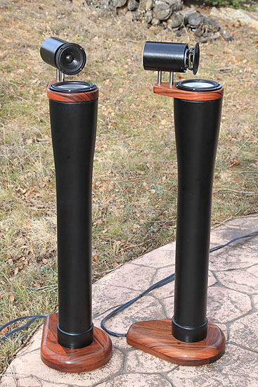
Progress!
Now I have abandoned the assymetric baffle shape for a more traditional. It's still dipole/open baffle and new dimensions are: 180x26cm. The array is offset so cc of the driver to the small side is 8cm. I've experimented before quite a bit with different sizes and offsettings, and became so fond of the (possible) soundstage with one very small side (facing towards center). The more centered array on the baffle, the less depth was my impression. So aiming for this I came up with these dimensions in edge. It's made to get a good dispersion as high as possible and still not loose too much bass. So according to the excellent paper of Rudolf Finke (thanks Juhazi), off setting is a good way of handle things when the baffle needs to be a bit more than 3 times the driver size. Maybe you gain a bit both low and high then?
So, big questions are:
1. Will this be ok from about 100-200Hz up to 4Hz EQ'ed?
2. How to think about the small vs the broad side? Good or bad with offset?
3. What sort of filter/EQ (if this is a good start)?
Measurements as before (UMIK-1, REW), outdoors, 3m.
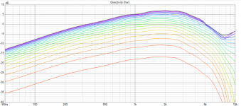
0-90 degress small side:

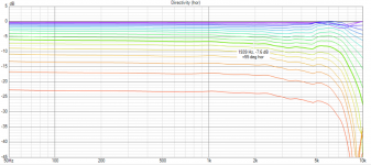
0-90 degress broad side:

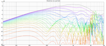
on axis+15 degress off axis on small and broad side:

Any other comments or ideas are welcome!
Now I have abandoned the assymetric baffle shape for a more traditional. It's still dipole/open baffle and new dimensions are: 180x26cm. The array is offset so cc of the driver to the small side is 8cm. I've experimented before quite a bit with different sizes and offsettings, and became so fond of the (possible) soundstage with one very small side (facing towards center). The more centered array on the baffle, the less depth was my impression. So aiming for this I came up with these dimensions in edge. It's made to get a good dispersion as high as possible and still not loose too much bass. So according to the excellent paper of Rudolf Finke (thanks Juhazi), off setting is a good way of handle things when the baffle needs to be a bit more than 3 times the driver size. Maybe you gain a bit both low and high then?
So, big questions are:
1. Will this be ok from about 100-200Hz up to 4Hz EQ'ed?
2. How to think about the small vs the broad side? Good or bad with offset?
3. What sort of filter/EQ (if this is a good start)?
Measurements as before (UMIK-1, REW), outdoors, 3m.
0-90 degress small side:
0-90 degress broad side:
on axis+15 degress off axis on small and broad side:
Any other comments or ideas are welcome!
Progress!
Now I have abandoned the assymetric baffle shape for a more traditional. It's still dipole/open baffle and new dimensions are: 180x26cm. The array is offset so cc of the driver to the small side is 8cm. I've experimented before quite a bit with different sizes and offsettings, and became so fond of the (possible) soundstage with one very small side (facing towards center). The more centered array on the baffle, the less depth was my impression. So aiming for this I came up with these dimensions in edge. It's made to get a good dispersion as high as possible and still not loose too much bass. So according to the excellent paper of Rudolf Finke (thanks Juhazi), off setting is a good way of handle things when the baffle needs to be a bit more than 3 times the driver size. Maybe you gain a bit both low and high then?
So, big questions are:
1. Will this be ok from about 100-200Hz up to 4Hz EQ'ed?
2. How to think about the small vs the broad side? Good or bad with offset?
3. What sort of filter/EQ (if this is a good start)?
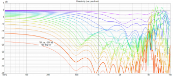
Measurements as before (UMIK-1, REW), outdoors, 3m.
0-90 degress small side:
View attachment 437493
0-90 degress broad side:
View attachment 437494
on axis+15 degress off axis on small and broad side:
View attachment 437495
Any other comments or ideas are welcome!
@diypole mentioned that dipole arrays are worth a look here: https://www.diyaudio.com/community/threads/another-improved-array-sep-2022.390605/post-7131505
I'm astonished that more people aren't doing this. The sims look absolutely ridiculous.
As time has marched on, I've noticed that dipole fans have been going for narrower and narrower and narrower baffles. For instance, the dipoles designed by Linkwitz in the 90s were nearly a foot in width, and his last dipole was just large enough for the drivers themselves.
@CharlieLaub has been doing some cool stuff with dipoles with NO baffle
Here's some sims of a dipole line array that I did yesterday, using VituixCad (the instructions on how to model this were posted by @kimmosto here:
Attached are the predicted horizontal polars and vertical polars for a dipole line array. I did it yesterday, if I recall correctly it's 7.5cm wide with eleven 2.5" drivers. I've included the normalized and un-normalized responses.
It requires filtering to become flat, so DSP is a must. But it provides nearly ideal directivity using a baffle that's 7.5cm wide!!
Another intriguing thing about it, is that you get vertical directivity control, even with a very short array. IE, you would need an array that's 1.7 meters long to control directivity down to 200HZ if it's a monopole, but a dipole array of almost any length will do the same. It really just comes down to how much power handling you need; the more output you need, the longer an array you'll want. (Note that maximum output at high frequency is largely limited by the maximum output of a single element, because high frequency sources do not combine.)
I think one could improve on these results quite a bit if they power tapered the array, but I do not see any way to do that in Vituixcad. (I assume that it's not possible to combine individual dipole sources in Vituixcad like you can with monopole sources. I may be wrong.)
If I were going to design one of these things in real life, I think I'd figure out the power tapering in Vituixcad, modeling the array as a monopole, and then I'd use the narrowest baffle that I could live with.
Shower thought:
A few weeks ago, someone on here demonstrated that the pipe behind the full range driver in the LX Mini really isn't doing anything.
If true, then one could probably make an interesting "LX Mini - ish" speaker by putting a dipole line array above the monopole.
Basically, Kimmo demonstrated years ago that you can get a cardioid response by combining a dipole and a monopole. So one could increase the power handling and the output of the LX Mini by using an array of full range drivers, instead of a single one.
I believe "the catch" would be that the array would need to be relatively short; if it's too long, then you'd get a bizarre vertical beamwidth due to the distance from the monopole to the dipole.
Attachments

Excellent work, those are sweet sims!
It wasn't until around 2010 that processing power allowed sims for dipole radiation on and off axis to be generated. At that point it became evident that the less baffle the better. I remember precisely when Linkwitz published the sims on his website for a driver in free air vs baffles of different widths. It was the data so many of us had wanted for many years. Figure A3-5 on this page. Linkwitz models More in depth analysis was added in the years that followed.
Excerpt A3-5 'The data are presented as frequency normalized on- and off-axis response curves for different radius of the flat baffle.
I thank Tim Mellow and Leo Karkkainen for generating the graphs, which required many hours of computer time. The graph for b=8a had to be truncated at ka = 5 because each data point took hours to calculate. The curves approach the infinite case.
Leo is still experimenting with ways to speed up the calculations for a piston in an open rectangular baffle of specified aspect ratio, which turns the analysis into a 3-dimensional problem. They have derived exact formulas, but the computational effort is immense.'
Above the crossover point, the ability of the monopole to cancel the rear wave of the fullrange and create a cardioid response diminishes with the slope of the crossover. The pipe is generally filled with acoustic absorption to prevent a hot spot if the speaker is close to a rear wall.
A 4" driver will begin to beam around 1,125hz. A 4" free air dipole and monopole will have equivalent output at 1,166hz. Above that point the rear output of the dipole is a separate source not available to the monopole. At 3200hz the dipole is capable of 9db more output than the monopole. As the driver begins to beam to the rear reflective surfaces directly behind it become an issue, which SL tried to mitigate with the pipe.
A 4" driver will begin to beam around 1,125hz. A 4" free air dipole and monopole will have equivalent output at 1,166hz. Above that point the rear output of the dipole is a separate source not available to the monopole. At 3200hz the dipole is capable of 9db more output than the monopole. As the driver begins to beam to the rear reflective surfaces directly behind it become an issue, which SL tried to mitigate with the pipe.
I'm combining a dipole and monopole for the woofer section of my current build. The use of them together with wide overlap of the frequency range they're covering to produce a cardioid response is intriguing. A short full range line with monopoles in the center and dipoles on the ends has me thinking now also.