I want to roll the (many) NE5532 opamps in my sony CDP-X505 ES players output stage. I've scanned its audio board schematics and color marked its opamps. Have a look here ")
http://www.beichel.at/x505es/audioboard_schematic_x505.gif
As you can see there are some dual and some single ops there (the "mix" ones are single i assume). Can you tell me which ones can be safely replaced w/ national's LM4562 or an equivalent (i have an eye on these and could get them for a good price) for better sound quality? I have heard that AD826 or OPA627 would be good, too.
According to http://babelfish.altavista.com/babe...01.hp.infoseek.co.jp/cdp777esa/cdp777esa.html
these 3-per-channel opamps are for "in buffer / GIC shape / LowPassFrequency" Well, i know what a LPF is but the other two functions? Would be glad if you could help me understand this better!
Also, the IC607 seems to be a single opamp for DAC power supply, is this correct? (+5V) Would it be a sound improvement to swap this one, too?
According to the above website: the two "final" opamps (OPA27GP) are IC405, IC505: for DC servo - Don't think these dc servo ops should be removed.
Problem is, i've not that much experience in modding, but eventually i'll get a few DIP8 socket so i can swap opamps easily.
A big THANK YOU in advance!
Regards
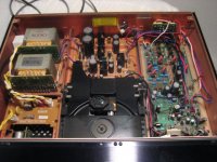
PS. further pics: http://www.beichel.at/x505es
PS. The Sony X555, X557, X777, X779 and 707 have quite similar output boards, so If someone has successfully rolled opamps there, would be glad to hear from you!
http://www.beichel.at/x505es/audioboard_schematic_x505.gif
As you can see there are some dual and some single ops there (the "mix" ones are single i assume). Can you tell me which ones can be safely replaced w/ national's LM4562 or an equivalent (i have an eye on these and could get them for a good price) for better sound quality? I have heard that AD826 or OPA627 would be good, too.
According to http://babelfish.altavista.com/babe...01.hp.infoseek.co.jp/cdp777esa/cdp777esa.html
these 3-per-channel opamps are for "in buffer / GIC shape / LowPassFrequency" Well, i know what a LPF is but the other two functions? Would be glad if you could help me understand this better!
Also, the IC607 seems to be a single opamp for DAC power supply, is this correct? (+5V) Would it be a sound improvement to swap this one, too?
According to the above website: the two "final" opamps (OPA27GP) are IC405, IC505: for DC servo - Don't think these dc servo ops should be removed.
Problem is, i've not that much experience in modding
, but eventually i'll get a few DIP8 socket so i can swap opamps easily.A big THANK YOU in advance!
Regards
PS. further pics: http://www.beichel.at/x505es
PS. The Sony X555, X557, X777, X779 and 707 have quite similar output boards, so If someone has successfully rolled opamps there, would be glad to hear from you!
Sony engineering at its best. Analog stage corrected in every possible way to reconstruct a proper sine-way (even it time domain), while adding a current boost and DC servo at the output. Not a single coupling cap in the whole path...
I have very similar output in my Denon, where I don't have mosfets in the output for current boost / low output impedance... However, I paralleled two halves of the AD826 (2 buffers working in parallel)... The sound is clean, easy to listen to - but lifeless!!! Ironed-out, boring, but still pleasant on the ear. I can see how people who never listened to live performances, or never experienced the sound of the recording master in a studio, can appreciate this kind of sound and be perfectly happy.
You have 2 options; upgrade the existing stage, or add external differential-to-single-ended output stage. Install the IC sockets and try different combinations of AD826, LM4562, OP275. OPA627 is ridiculously expensive and I refuse to use it (in fact, I ditched BB / IT altogether for this reason). Try AD8066 which sounds even better if properly decoupled, and is a DUAL OP.
Regards,
Boky
I swaped almost all of the opamps in my Sony 505 (apart from the OP27 which is for DC-offset control) with op213(2)4, OP275 (filter), LM6172 (IC4/501 with local decoupling, for I/U conv) and that kind of stuff but couldn't really hear much of a difference. I also upgraded the analogue power supply caps and added more capacitance directly on the board (C617-620). It was a lot of work to desolder all the opamps and put some DIP8 sockets in. The DIP-sockets don't really fit but you can make it work. I don't think it was worth it.
What really made a difference imho was to replace the digital decoupling caps around the DAC with os-cons.
All in all I was never satisfied with the sound of the Sony although I really like its mechanical appearance. It's a pity! May be the output stage is to complex? Or some jitter issues caused by multiple clocks?
I would say start with the digital and analogue power supply upgrades and than may be think a about a new (opamp less?) output stage.
joe
rabbitz said:The AD825 is a good choice on the output stage and use them on CDP-X55ES as well as CDP990.
Renewing some of the caps to feed these op amp can help as well.
Thank you. Does the X55ES have this many 5532s in its output stage, too? Did you just replace 2 of them w/ AD825, if yes, which ones (4/503 or 4/504 - see schematic)?
Can you describe how the "sound" did change? I.e dynamics, soundstage, resolution.... Hm, i like to have the sound of "digital" away, i don't like hyper-detail or absolutely pinpoint imaging. But i adore an analog, engaging, dynamic sound. Would be great if the 825 help in that way?
Problem is, like Extreme_Boky said, sometimes if you swap opamps the sound becomes too "clean" or un-involving. Of course this is a subjective thing, hm.
joe said:(...) It was a lot of work to desolder all the opamps and put some DIP8 sockets in. The DIP-sockets don't really fit but you can make it work. I don't think it was worth it.
What really made a difference imho was to replace the digital decoupling caps around the DAC with os-cons.
All in all I was never satisfied with the sound of the Sony although I really like its mechanical appearance. It's a pity! May be the output stage is to complex? Or some jitter issues caused by multiple clocks?
I would say start with the digital and analogue power supply upgrades and than may be think a about a new (opamp less?) output stage.
joe
Great insight information thank you. I love the mechanic build quality of these Sony players too, i mean they might have one of the best optical pickup mechanisms ever built in consumer electronics. Accuphase uses the cd drive, too. The laser is hovering in a magnetic field or some thing, no cheap white plastic gears making noise
Regarding the digital and analogue PSU upgrades, can you tell me which ones you swapped exactly? On the PSU board http://www.beichel.at/x505es/power-board1.jpg there are two ELNA Duorex, the smaller ones are black [M] Matsushita/Panasonics and brown (Elna?) ones. Which caps (brand, specs) did you put in instead?
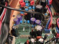
And the caps around the DAC: Like C614 (the biggest one, right in the center http://www.beichel.at/x505es/audio-board1.jpg) is not a decoupling cap am i right? It is probably used as a electric buffer for smoothing out the power supply?
So which ones are exactly the decoupling caps, can you tell me?
Did you just swap them with sanyo os-cons with the same specs, or is more uF or so generally considered a good thing to do? Would be great if you had your 505 still around you, even if you are/were not that satisfied with its sound.I'm new to DIY-modding, so far i only installed a Lclock XO2 w/ PSU and I'm very pleased with the result, the sound's got much more dynamics, attack, liquid lows mids and highs. Even if these Sonys seem to have 2 clocks, some people say that the 16Mhz is derived (calculated: 1/3) frequency from the 45Mhz XO clock supply. And wow, NOW listening fatigue is completely gone, instead you will be foot-tapping all the time as the music's timing is so much better!
Your help regarding the cap replacements is appreciated! Thanks..
aircondition said:
Thank you. Does the X55ES have this many 5532s in its output stage, too? Did you just replace 2 of them w/ AD825, if yes, which ones (4/503 or 4/504 - see schematic)?
Can you describe how the "sound" did change? I.e dynamics, soundstage, resolution.... Hm, i like to have the sound of "digital" away, i don't like hyper-detail or absolutely pinpoint imaging. But i adore an analog, engaging, dynamic sound. Would be great if the 825 help in that way?
Problem is, like Extreme_Boky said, sometimes if you swap opamps the sound becomes too "clean" or un-involving. Of course this is a subjective thing, hm.
I tried replacing the 4 opamps (IC4/507 IC4/506 in X55ES) firstly with OPA2134 but was way too much, shouty and over the top but was better when only IC4/507 changed (last opamp) and the rest left as original (in this case 5532DD).
The best result was using AD825 on Brown Dog adaptors for IC4/507 and the remainder left stock. The sound became very smooth, great detail and seemed to dig deeper in the bottom end. A more controlled natural sound without the tizz and boom excitement.
Output caps C4/514 were changed to BG NX 47uF 6.3V and the by-pass C4/515 were removed. Power supply caps C508/C509 (I think) that fed IC4/507 were changed to Nichicon FG 47uF 50V. The supply caps C4/556 were changed to Panasonic FC.
Everything else is stock except to Toslink changed to an electrical digital out.
The digital decoulpling caps around the dac are: C401, C403, C503, C408, C508, C630, you get the idea.
When it comes to digital decoupling the quality of the caps and short leads/tracks are more important than quantity. I think I replaced them with 100uF oscons because I had them at hand. It's probably worth to solder some 10-100nF smd caps diretly at the pins where possible.
I can't remeber exactly what I did to the power supply. I probably replaced the caps with Panasonic FCs, apart from the main reservoir caps because I had nothing equivalent. I need to open the lid and have a look for more details.
I haven't touched the opamps yet but upgraded some caps in the analogue PSU to Pana FC w/ same values. The improvement is a smoother yet cleaner sound and lots more depth in the soundstage. Now i'm very happy since the total cost for these 4 caps was about 1,50 USD and yet the improvement is so easily heard!
Next i'll try to swap some digital decoupling caps, should I replace the caps using approx. the same values (ie 100uF/25V/50V etc) even if the voltage in the digital circuits is just 5 volts? One might think that it would be best to use something near the circuits voltage (thinking of 6.3, 10 or 16V). Dunno know why Sony uses such high volt caps, there could be a reason?
The overall suggestion in digital decoupling seems to use low-ESR caps. According to Pana FC datasheet the 6.3V/100uF has imp. of 0.80Ù @100kHz, the 16V/100uF has 0.350 (less than half) 16V/220uF is again much lower: 0.117.
The Ripple current is higher w/ higher volts & capacitance, is this a good thing here?
So which caps could work best in digital decoupling application?
* low-V (ie 6,3V) with higher esr
* middle-V (ie 16 or 25V) with lower esr
* low-V and higher capacitance (220uF or more instead of the 100uF)
I tried hard to "extract" the answer from diyaudio's long and winding threads. Thank you.
While I agree that rolling the op-amps may bring improvements (with a bit of luck) the results are highly unpredictable though. Combining PSRR, CMRR, noise etc of the op-amp with a specific layout, power supply and application schematic hardly gives an indication about what was achieved.
I'd like to suggest a different approach: a closer look to the filter caracteristics (type, order, cutoff freq.) and optimize these first before spending money on 12 single op-amps and adaptors or 6 dual op-amps. Most likely the improvements will be quite noticeable and you'll have the chance to control/corelate the results to your liking...
I'd like to suggest a different approach: a closer look to the filter caracteristics (type, order, cutoff freq.) and optimize these first before spending money on 12
single op-amps and adaptors or 6 dual op-amps. Most likely the improvements will be quite noticeable and you'll have the chance to control/corelate the results to your liking...There is so much opamp silicon there. it will be costly to replace it all with "audiophile" type opamps for a good but small improvement. It would be far better to simplify it all and use discrete Class A silicon, use a Zap MkII output stage from LC Audio, all the works done and it even has the hook diagram up for the CXD2562 dac.
I played with "audiophile" opamps, while you can get improvements, they don't come anywhere near the Zap MkII. Much simpler, all discrete, class A, dc coupled, and with separate shunt regulated supply. And it blows all the "audiophile" opamps away!
http://www.lcaudio.com/index.php?page=43
http://www.lcaudio.com/index.php?page=6
Cheers George
Attachments
ZapfilterII - seconded
Couldn't agree more. I have the ZapfilterII in my Marantz CD-67SE and it made an enormous improvement.
In my implementation I put a 3rd-order low-pass passive filter between each voltage output of the DAC and input of the Zap. The DAC used unusually has unfiltered raw PWM outputs unlike most.
(A simple RC and then RCRC did the job too but sounded a bit rolled off, unlike the RCLC I settled on, which is flat to 20kHz.)
Fitting the 20VA toroid in was a challenge.
georgehifi said:There is so much opamp silicon there. it will be costly to replace it all with "audiophile" type opamps for a good but small improvement. It would be far better to simplify it all and use discrete Class A silicon, use a Zap MkII output stage from LC Audio, all the works done and it even has the hook diagram up for the CXD2562 dac.
I played with "audiophile" opamps, while you can get improvements, they don't come anywhere near the Zap MkII. Much simpler, all discrete, class A, dc coupled, and with separate shunt regulated supply. And it blows all the "audiophile" opamps away!
http://www.lcaudio.com/index.php?page=43
http://www.lcaudio.com/index.php?page=6
Cheers George
Couldn't agree more. I have the ZapfilterII in my Marantz CD-67SE and it made an enormous improvement.
In my implementation I put a 3rd-order low-pass passive filter between each voltage output of the DAC and input of the Zap. The DAC used unusually has unfiltered raw PWM outputs unlike most.
(A simple RC and then RCRC did the job too but sounded a bit rolled off, unlike the RCLC I settled on, which is flat to 20kHz.)
Fitting the 20VA toroid in was a challenge.
Joe ..., i like the sound of the Hitachi MOSFET's
Aircondition
Regarding the op-amps in the analog stage, i have very good result using the Burr Brown OPA2604 as replacement for IC401/IC501, IC402/IC502 & IC404/IC504 all the ones directly in the signal path ..., OPA2604 delievers a very nice sonic performance, for instance an precise, strong and solid bass, the highs with a hint of "tube glow"
I have not changed usage of NE5532 for the LP filter(IC403/IC503), I did try other types of op-amps,
but they did result in DC Offset at the outputs
Regarding the Reg. PSU. op-amp's
IC607 used for the +5VDC "Analog Power" reg. psu and the IC921 located in the main power supply for the +/- 15VDC reg. psu.., at both locations i have used AD812 among other it has -120dB THD to more than 40KHz , sonic improvement from usage of the NE5532 is actully an impressive amount
A note regarding the IC921
I know i use the op-amp slightly over the the max. rating of the supply voltage..., i have added a small heatsink on the top of the op-amp, so no worry about that issue.
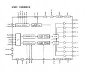
Futher more ..., ever noticed that the CXD2562Q DAC has an optional function ?
Digital phase inverter can be made by lifting pin no. 51 (DPOL) just needed to add an switch or relay for selecting hi/lo state
Usage of this feature can for some recordings make the overall performance of the stereo, raise to a higher level
Same metode goes for CXD2552 its pin no. 10 (POL)
Cheers M8's
Ps. got a pair of Martin Logan CLS which is a nice "tool" to investigate the small matters
Aircondition
Regarding the op-amps in the analog stage, i have very good result using the Burr Brown OPA2604 as replacement for IC401/IC501, IC402/IC502 & IC404/IC504 all the ones directly in the signal path ..., OPA2604 delievers a very nice sonic performance, for instance an precise, strong and solid bass, the highs with a hint of "tube glow"
I have not changed usage of NE5532 for the LP filter(IC403/IC503), I did try other types of op-amps,
but they did result in DC Offset at the outputs
Regarding the Reg. PSU. op-amp's
IC607 used for the +5VDC "Analog Power" reg. psu and the IC921 located in the main power supply for the +/- 15VDC reg. psu.., at both locations i have used AD812 among other it has -120dB THD to more than 40KHz , sonic improvement from usage of the NE5532 is actully an impressive amount
A note regarding the IC921
I know i use the op-amp slightly over the the max. rating of the supply voltage..., i have added a small heatsink on the top of the op-amp, so no worry about that issue.
Futher more ..., ever noticed that the CXD2562Q DAC has an optional function ?
Digital phase inverter can be made by lifting pin no. 51 (DPOL) just needed to add an switch or relay for selecting hi/lo state
Usage of this feature can for some recordings make the overall performance of the stereo, raise to a higher level
Same metode goes for CXD2552 its pin no. 10 (POL)
Cheers M8's
Ps. got a pair of Martin Logan CLS which is a nice "tool" to investigate the small matters
PMik, thanks for your detailed reply In the meantime I have already modified the x505 with the Zapfilter MK2 discrete output stage -- no need for swapping the OPAs in the analog stage anymore
Thx for the notion of improving upon IC607 and IC921, this really looks promising. I assume the AD812 is available in DIP8 package so a straight swap should be possible, will be looking into it soon.
ATM my primary goal for improving the players sonics is the ZAPFilter PSU. Sigma22 should be easy to build, but not that easy to fit inside the player. An external enclosure should be possible to do, but is not my preferred solution. Please look at my measured voltage readings of the stock supply. This is about 23V symmetrical, plus an +23 V aux supply. I have the 230V european version.
@Glenn2: You live in England, can you eventually verify that this is correct? Or do you have half of my measured 23V, over at headfi a user suggested that 23V is too high (double!). My zapfilter board gets quite hot, but i assume I have my wiring correct, as I dont get any sound problems with my current setup.
Second, I think it should be possible to use 2 sercal Spower regs with +24 and -24 volts, heatsinked (do you know how much current the zapfilter draws?) and "injecting" it into the current position of the main filter caps on the stock zapfilter psu (removing diodes etc from it, only leaving the two 56R 5W resistors on it) - Q: how do i wire the AUX ? Do you have some suggestions ?
Any help is greatly appreciated. Thank you!
In the meantime I have already modified the x505 with the Zapfilter MK2 discrete output stage -- no need for swapping the OPAs in the analog stage anymore Thx for the notion of improving upon IC607 and IC921, this really looks promising. I assume the AD812 is available in DIP8 package so a straight swap should be possible, will be looking into it soon.
ATM my primary goal for improving the players sonics is the ZAPFilter PSU. Sigma22 should be easy to build, but not that easy to fit inside the player. An external enclosure should be possible to do, but is not my preferred solution. Please look at my measured voltage readings of the stock supply. This is about 23V symmetrical, plus an +23 V aux supply. I have the 230V european version.
@Glenn2: You live in England, can you eventually verify that this is correct? Or do you have half of my measured 23V, over at headfi a user suggested that 23V is too high (double!). My zapfilter board gets quite hot, but i assume I have my wiring correct, as I dont get any sound problems with my current setup.
Second, I think it should be possible to use 2 sercal Spower regs with +24 and -24 volts, heatsinked (do you know how much current the zapfilter draws?) and "injecting" it into the current position of the main filter caps on the stock zapfilter psu (removing diodes etc from it, only leaving the two 56R 5W resistors on it) - Q: how do i wire the AUX ? Do you have some suggestions ?
Any help is greatly appreciated. Thank you!
Attachments
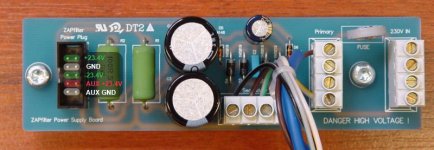
Hi, yes the Zapfilter board gets very hot, as does the PSU board. All class A...
The PSU board is for rectifying and smoothing (the big resistors and caps form an RC filter). The regulators are on the Zapfilter2 board itself. These are high-quality shunt regulators! You don't want to be adding any more regulators.
Most of the parts on the Zapfilter board are for voltage regulation, DC servo, muting, etc. Not very much of it is actually directly in the signal path.
If I get a chance tonight I will measure the voltages.
Re: ZapfilterII - seconded
Hi glenn, thanks for the quick reply. Ok the shunt reg on the zapfilter board is good news - I think I didn't read LC audios description carefully enough. Would be great if you could measure the voltages on your psu board if you have time Thank you.
Because according to this post over at headfi one can definitely improve the zapfilter's sound using the sigma22 So lets try it!
Glenn, do you know if the Sony CXD2562Q has "unfiltered outputs" too (i cannot find a valid datasheet for it) ? Or can we assume that it has some sort of filtering inside.. and nothing else needs to be done. See the audioboard schematic at my website:
http://www.beichel.at/x505es/audioboard_schematic_x505.gif
I can soon create a picture showing how I currently have connected my zapfilter after the DAC chip..
@Zapfilter users, join in and keep the 'thread goin'
Hi glenn, thanks for the quick reply. Ok the shunt reg on the zapfilter board is good news - I think I didn't read LC audios description carefully enough. Would be great if you could measure the voltages on your psu board if you have time
Thank you.Because according to this post over at headfi one can definitely improve the zapfilter's sound using the sigma22
So lets try it!Glenn2 said:...In my implementation I put a 3rd-order low-pass passive filter between each voltage output of the DAC and input of the Zap. The DAC used unusually has unfiltered raw PWM outputs unlike most.
(A simple RC and then RCRC did the job too but sounded a bit rolled off, unlike the RCLC I settled on, which is flat to 20kHz.)..
Glenn, do you know if the Sony CXD2562Q has "unfiltered outputs" too (i cannot find a valid datasheet for it) ? Or can we assume that it has some sort of filtering inside.. and nothing else needs to be done. See the audioboard schematic at my website:
http://www.beichel.at/x505es/audioboard_schematic_x505.gif
I can soon create a picture showing how I currently have connected my zapfilter after the DAC chip..
@Zapfilter users, join in and keep the 'thread goin'
- Status
- This old topic is closed. If you want to reopen this topic, contact a moderator using the "Report Post" button.
- Home
- Source & Line
- Digital Source
- OpAmp rolling in Sony CDP X505ES