I have read a lot of articles which emphasise the importance of matching the +/- input impedance of opamps in order to achieve low distortion.
My question is, is it necessary to match the +/- impedance for opamp buffers? An opamp buffer is one where the - input is directly connected to the output with a piece of wire, not a resistor.
I found it hard to match the impedance, DC or AC, especially AC impedance in circuits like Sallen-Key filters.
Regards,
Bill
op amp inputs show nonlinear input impedance if you look closely enough
can give measureable distortion - matching impedance seen by +,- inputs can help - sugested for fet inputs particularly since filter circuit impedances may be higher and their problem is nonlinear device-substrate parasitic C
it is possible to match filter component impedance with duplicate parts but not often done
don't really need to worry unless low order, smooth distortion charateristic at <0.01% levels bother you
Last edited:
I use a series resistor in the connection between output and -ve in. Not just for distortion reduction but also for improved DC offset - so the input bias currents give rise to the same voltage at each. I put around 100pF in parallel with this resistor so the input capacitance doesn't degrade the phase margin.
don't really need to worry unless low order, smooth distortion charateristic at <0.01% levels bother you
The lower the distortion the better it is.
In my BJT input power amp, when I slightly mismatched the differential input AC impedance seen from the input and the feedback I found the sound degraded.
In my 4 way active crossover with 14 stages, the ones with matching +/- input impedance show low DC offset of 0mV - 0.2mV, while those with large impedance mismatch show as much as 6mV!
I am trying to match the impedance at DC and don't worry about it at AC because it is too difficult.
The problem I had was that I don't know how to match the impedance of a buffer, i.e. the - input connects to the output.
I use a series resistor in the connection between output and -ve in. Not just for distortion reduction but also for improved DC offset - so the input bias currents give rise to the same voltage at each. I put around 100pF in parallel with this resistor so the input capacitance doesn't degrade the phase margin.
Interesting. I have never seen anybody published any circuits using this method.
I quickly drew it in LTSpice and it showed the same response, at least within the audioband.
When I get home, I can post a picture.
I use a series resistor in the connection between output and -ve in. Not just for distortion reduction but also for improved DC offset - so the input bias currents give rise to the same voltage at each. I put around 100pF in parallel with this resistor so the input capacitance doesn't degrade the phase margin.
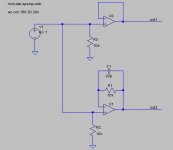
Is it like this?
Attachments
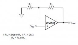
On top of the issue of differential input bias current causing DC offset, here is an extract taken from the opa2134 datasheet:
For lowest distortion with a source or feedback network which has an impedance greater than 2kW, the impedance seen by the positive and negative inputs in noninverting applications should be matched. The p-channel JFETs in the FET input stage exhibit a varying input capacitance with applied common-mode input voltage. In inverting configurations the input does not vary with input voltage since the inverting input is held at virtual ground. However, in noninverting applications the inputs do vary, and the gateto- source voltage is not constant. The effect is increased distortion due to the varying capacitance for unmatched source impedances greater than 2kW. To maintain low distortion, match unbalanced source impedance with appropriate values in the feedback network as shown in Figure 3. Of course, the unbalanced impedance may be from gain-setting resistors in the feedback path. If the parallel combination of R1 and R2 is greater than 2kW, a matching impedance on the noninverting input should be used. As always, resistor values should be minimized to reduce the effects of thermal noise.
For lowest distortion with a source or feedback network which has an impedance greater than 2kW, the impedance seen by the positive and negative inputs in noninverting applications should be matched. The p-channel JFETs in the FET input stage exhibit a varying input capacitance with applied common-mode input voltage. In inverting configurations the input does not vary with input voltage since the inverting input is held at virtual ground. However, in noninverting applications the inputs do vary, and the gateto- source voltage is not constant. The effect is increased distortion due to the varying capacitance for unmatched source impedances greater than 2kW. To maintain low distortion, match unbalanced source impedance with appropriate values in the feedback network as shown in Figure 3. Of course, the unbalanced impedance may be from gain-setting resistors in the feedback path. If the parallel combination of R1 and R2 is greater than 2kW, a matching impedance on the noninverting input should be used. As always, resistor values should be minimized to reduce the effects of thermal noise.
Attachments
The interesting thing is, if according to opa2134 datasheet, the buffer implementation is merely R2 = 0, which means R1 || R2 = 0, and 0 < 2k, so not matching is required.
This gave rise to my original question - do we need to match the + / - impedance of an opamp in a buffer?
This gave rise to my original question - do we need to match the + / - impedance of an opamp in a buffer?
Is it like this?
You have drawn your signal source as an ideal voltage source, which means that the + input is driven from a zero impedance. If there is a DC blocking capacitor somewhere between the source and the buffer that you haven't drawn, then you have matched the impedances at DC, but mismatched them at signal frequencies where the DC blocking capacitor is basically a short.
Matching the impedances at DC only makes sense when the bias currents are big enough to worry about. Are they?
A disadvantage of the extra resistor is that it also adds extra thermal noise. On the other hand, on some op-amps with base current compensation, such as the LT1028, the extra resistor helps to cancel the base current compensation circuit common-mode noise.
You have drawn your signal source as an ideal voltage source...
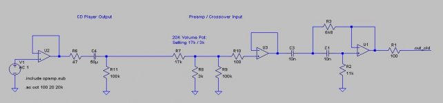
Here is a simplified drawing, ignoring the cable and the input RF shunt capacitor network. This is a simplified tweeter circuit I am building.
With volume pot, the impedance varies, and 17k / 3k is the normal position. I know I can not get it 100%, but I am trying to get the impedance as close as possible under normal (17/3) condition.
As for the Sallen Key, not, I don't know how to match the + /- impedance.
Attachments
Some opamps misbehave if set to unity gain and have zero resistance in the out to -IN pin.
The datasheet will usually specify a minimum resistance for that unity gain link.
Rather than trying to remember which datasheets mention the warning and the value, I adopt a 1k0 as my default out to -IN resistance for ALL unity gain opamps.
The datasheet will usually specify a minimum resistance for that unity gain link.
Rather than trying to remember which datasheets mention the warning and the value, I adopt a 1k0 as my default out to -IN resistance for ALL unity gain opamps.
I have been using opa627 for the tweeter and midrange crossover, and LM4562 for the woofer crossover. Both of them are unity gain stable. I have lately found that even for the woofer crossover, the opa627 sounds a lot better. But opa627 is about 10 times more expensive than LM4562.
Do you suggest that even for unity gain stable opamps you would put some resistance between the - input and the output? I don't know if there are any other drawbacks on top of more noise?
Do you suggest that even for unity gain stable opamps you would put some resistance between the - input and the output? I don't know if there are any other drawbacks on top of more noise?
You have drawn your signal source as an ideal voltage source, which means that the + input is driven from a zero impedance. If there is a DC blocking capacitor somewhere between the source and the buffer that you haven't drawn, then you have matched the impedances at DC, but mismatched them at signal frequencies where the DC blocking capacitor is basically a short.
Matching the impedances at DC only makes sense when the bias currents are big enough to worry about. Are they?
What you said makes good sense. It appears that I can get a few mV DC offset with LM4562, but at most 0.5mV with opa627, because the opa627 has a lower bias current.
For filter application, I can not see any possibility to match the + / - input impedance at AC. Getting them closer may be possible, but matching seems impossible.
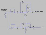
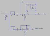
With your tips on impedance matching, I have now come up with this Sallen Key implementation, with + / - input impedance matched, both at DC and AC.
Is it the way you would do the impedance matching?
With less than 5pA input bias current of the opa627, is it worthwhile?
Without the impedance matching, I found 0mV - 0.2mV DC offset with opa627. This DC offset is not a concern. I am more concerned if distortion is increased with AC signals.
Is it the way you would do the impedance matching?
With less than 5pA input bias current of the opa627, is it worthwhile?
Without the impedance matching, I found 0mV - 0.2mV DC offset with opa627. This DC offset is not a concern. I am more concerned if distortion is increased with AC signals.
Attachments
Hi Bill, You could run a transient analysis on the circuit and do an fft to see what the effects on distortion are. Note that the distortion results will more than likely be better than real world, possibly by a large margin, but it will at least give you an idea whether it increases or decreases distortion.
I just lifted this out of my sim for my active crossover:
.tran 0 320m 220m 0.1u startup
.options plotwinsize=0
.param Freq=1000
.four {Freq} V(.out_standard_implementation)
.four {Freq} V(.out_matched_impedance)
.options ptrantau=1e-8 #I can't remember what that one does, but think it has to do with finding the dc operating point.
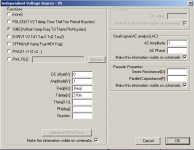
set your ac1 as per the attachment. change the param Freq=1000 to test the distortion at different frequencies.
You will need to comment out your .ac line. stick a ; on the front")
It will take a while (I found running for 320ms helps a lot with getting a clean result, you can try less if you want to speed it up.
When the sim has finished go to view spice error log and you will have the distortion analysis for each. right click on the waveform window and choose fft to do the fft plot.
I hope you didn't already know all this
edit: also to ensure more real world results make sure you put in some reasonable values for your caps ESR and ESL. for small film caps you could use say 16 ohms for Equiv Series Resistance and 6n for equiv series inductance.
Tony.
I just lifted this out of my sim for my active crossover:
.tran 0 320m 220m 0.1u startup
.options plotwinsize=0
.param Freq=1000
.four {Freq} V(.out_standard_implementation)
.four {Freq} V(.out_matched_impedance)
.options ptrantau=1e-8 #I can't remember what that one does, but think it has to do with finding the dc operating point.
set your ac1 as per the attachment. change the param Freq=1000 to test the distortion at different frequencies.
You will need to comment out your .ac line. stick a ; on the front
It will take a while (I found running for 320ms helps a lot with getting a clean result, you can try less if you want to speed it up.
When the sim has finished go to view spice error log and you will have the distortion analysis for each. right click on the waveform window and choose fft to do the fft plot.
I hope you didn't already know all this
edit: also to ensure more real world results make sure you put in some reasonable values for your caps ESR and ESL. for small film caps you could use say 16 ohms for Equiv Series Resistance and 6n for equiv series inductance.
Tony.
Attachments
Last edited:
Hi, Tony, long time no chat! How are you?
No, I have never done any fft. I only use LTSpice to model frequency response. By the way, do you need the opa627 model in order to obtain accurate analysis? Perhaps we shall meet, and I will soon have a first class system (OB active 4way) to show you, and you can show me your stuff and teach me how to do fft, etc. Out of topic here. Would you mind sending me some simple LTSpice file with your fft set up to my email? Thanks in advance.
No, I have never done any fft. I only use LTSpice to model frequency response. By the way, do you need the opa627 model in order to obtain accurate analysis? Perhaps we shall meet, and I will soon have a first class system (OB active 4way) to show you, and you can show me your stuff and teach me how to do fft, etc. Out of topic here. Would you mind sending me some simple LTSpice file with your fft set up to my email? Thanks in advance.
- Status
- This old topic is closed. If you want to reopen this topic, contact a moderator using the "Report Post" button.
- Home
- Amplifiers
- Chip Amps
- opamp matching +/- input impedance necessary for buffer?