While what you have is very interesting, would have to find a way to keep the same input impedance (or something very similar).
So you removed/bypassed the 100n and reconnected the ground leg of the 4.7k at the 10u. Not really new and I fail to see the advantages vs removing capacitors alltogether (and adding a servo in case offset is an issue....).
So you removed/bypassed the 100n and reconnected the ground leg of the 4.7k at the 10u. Not really new and I fail to see the advantages vs removing capacitors alltogether (and adding a servo in case offset is an issue....).
I don't think that wouldn't work in practice although it would in simulation. It's relying on the input source to define the DC conditions. An AC coupled source wouldn't bias the opamp correctly.
I can't see or visualise what diegomj1973 has done.
These are my thoughts on it all...
to keep the midband input impedance similar seems to imply that the 4K7 and 1K2 still define that parameter. If the 0.1uf were bootstrapped then the input impedance would rise.
In simulation you can "flip" the voltage source physically through 180 degrees and make use of applying the input to the inverting terminal. Again thats a case of works in simulation but not in practice.
I wonder if the 10K output resistor could play a part. We are assuming its a passive non-contributor... so why include it at all.
I haven't been able to figure out any other topology to achieve this....
")
Indeed, the DC offset of the source is repeated at the output (+its own)I don't think that wouldn't work in practice although it would in simulation. It's relying on the input source to define the DC conditions.
Which may bring us back to square one...An AC coupled source wouldn't bias the opamp correctly.
I have not looked into inverting configurations, I'm not sure if it was a prerequisite not to invert phase.
There seems to be no solution. I have tried all possible combinations (also the 10k) - also inverting inputs to use inverting mode ...
We are spending time for a solution which
* may or may not exist
* perhaps runs only in simulation
* perhaps is using anomalies of some opamps (internal bias etc.)
So it's time to show results...
We are spending time for a solution which
* may or may not exist
* perhaps runs only in simulation
* perhaps is using anomalies of some opamps (internal bias etc.)
So it's time to show results...
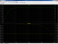
Looking at the first post the response has to be around 3db down at 7hz....
I was thinking... but didn't get anywhere... that the requirement of "the output voltage has to be developed across the 10k" doesn't actually mean the 10k has to be connected to the opamp output.
More thoughts Does this new circuit configuration allow for full (lets say rail to rail) output voltage to be developed at all frequencies within the passband ?
I was thinking... but didn't get anywhere... that the requirement of "the output voltage has to be developed across the 10k" doesn't actually mean the 10k has to be connected to the opamp output.
More thoughts
Does this new circuit configuration allow for full (lets say rail to rail) output voltage to be developed at all frequencies within the passband ?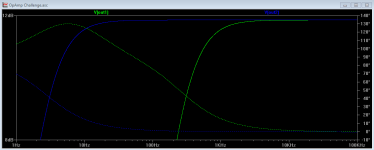
A well known formula for RC filter calculation is
fc=1/(2*3.1415926*R*C)
So if we use the 10µF capacitor with the input impedance which should be about 5.9 kOhm the -3dB cut off frequency is about 2.67 Hz which does not correspond with the presented graphs from diegomj1973.
My post #75 has an input impedance of about 2.4 kOhm which gives us -3dB at 6.63 Hz. => exactly what all graphs from diego are showing.
Conclusions:
* the 10µF capacitor is not connected at the input stage
* or diegomj1973 measurements are wrong and his circuits input impedance is 2.4kOhm and not 5.9kOhm.
If it helps: the 10K resistor is connected directly between pin 6 and 0 volts (in both variants: the common and modified). It may be another value, too: to make it more generic.
Tested with TL071, TL081CP, LM741.
It works in real conditions and simulations.
I had uploaded a video on YouTube that showed a better response at low frequencies. However, I had to delete when I realized the possibilities this could offer myself.
regards
Tested with TL071, TL081CP, LM741.
It works in real conditions and simulations.
I had uploaded a video on YouTube that showed a better response at low frequencies. However, I had to delete when I realized the possibilities this could offer myself.
regards
I'm off to the patent office.
Take this one with you too, do they pay well in Holland?
Attachments
Teehee ... Its really fun to see everyone "run around the bush" by the effervescent mendacity of Mr. Diego. He did a U-Toob video, don't we know! But "had" to remove it ... 'cuz it might be something that'd profit him.
LOL.
Its just as much fun to watch the trolls "trawling" the goobers as the goobers being trawled by the trolls.
GoatGuy
LOL.
Its just as much fun to watch the trolls "trawling" the goobers as the goobers being trawled by the trolls.
GoatGuy
There seems to be no solution. I have tried all possible combinations ...
There are a whole bunch of possible combinations.
Did you have an algorithm that you used?
Mooly:
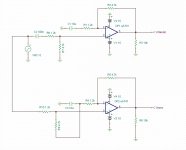
I'm just learning to use spice, thinking it might help me understand your previous response, the one where you lifted the input signal return to the top of the 10uf cap.
I still don't get it. The frequency response at that node (the top of the cap) doesn't seem to change, although the magnitude looks like it increases. How does this work to lower the pass band?
I'm obviously missing something very important here.
on edit: Doh! It's a .1uF cap, not a 10uf!
Last edited:
Mooly:
I'm just learning to use spice...........
You're not the only one
Knowing now that the 10K doesn't figure in it all I can't see a solution. If the input has to be AC coupled, then as I see it pin 3 needs to see 5.9k to ground both to define the input impedance and to set the DC conditions. Bootstrap it in any way and you lose that...
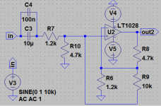
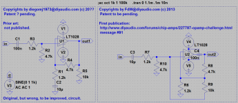
This is my latest (and probably final) schematic; I did find a legitimate usage for the 100nF capacitor (although not in the signal path or the feedback-path). The scheme now has been decorated with (almost) legal annotations. Last night the patent office was closed, I will try again coming night
P.s. I would like to see some comments (as he did in other cases), and maybe calculations, from diegomj1973.
P.s. I would like to see some comments (as he did in other cases), and maybe calculations, from diegomj1973.
Attachments
- Status
- Not open for further replies.
- Home
- Amplifiers
- Chip Amps
- Opamp challenge