But they are within the feedback loop so wouldn't worry too much. My headphone amp with AD8610/BUF634, OPA627/BUF634, sounds quite nicejanneman said:Surely you know that those buffers have quite higher distortion than those fantastic opamps, right?
")
It depends what you mean by better. I always try to keep the connection between the source and my ears as short as possible. Unfortunately, we need amps and speaker and stuff .
Those buffers are required if you want to drive low impedance head phones for instance, because the opamp can't cope with such a low load. For driving a power amp it is not really necessary. There are people using just a volume pot between the CD player and the power amp. You can't get much simpler than that.
What I would do in your place is build the board, initially leave out the buffer, listen to it, then put in the buffer, listen again.
And let us know.
Jan Didden
. Those buffers are required if you want to drive low impedance head phones for instance, because the opamp can't cope with such a low load. For driving a power amp it is not really necessary. There are people using just a volume pot between the CD player and the power amp. You can't get much simpler than that.
What I would do in your place is build the board, initially leave out the buffer, listen to it, then put in the buffer, listen again.
And let us know.
Jan Didden
janneman said:
Are you sure you need R5 & R15? It negates the effect of the buffer. What's the value of those resistors?
It is most surely to isolate the feedback circuit from capacitive
loads. Walt jung recommends to use such resistors, small value
of course, in his articles on opamp + buffer. I can't remember
if the datasheet recommends it too, and I am too lazy to check
that right now.
Otherwise, the schematics looks like the one by PMA and he
uses 50 Ohms at the output and a 50 Ohm termination at
the receiving end. He claims it sounds better to do that also
for line level signal, as far as I can remember.
Alcaid, it is a feedback amplifier, if you use ground plane or ground fill be careful with strayed capacitances, at least from the inverting inputs and from the outputs. Though everything still could be well with a few tens of pF at both points... And though you can always stick with Zobel...  My last experience tells me that even without feedback the things with analog circuits may (more info soon) be better without ground plane.
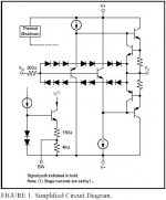
Does anyone know the harmonic distortion performance of BUF634 (open loop)?
Pedja
My last experience tells me that even without feedback the things with analog circuits may (more info soon) be better without ground plane.Does anyone know the harmonic distortion performance of BUF634 (open loop)?
Pedja
My diamond buffer had less than 0.008% so I'll gather that BUF634 has less than 0.1%, probably less than 0.01%. The datasheet says nothing about this.
Christer said:
It is most surely to isolate the feedback circuit from capacitive
loads. Walt jung recommends to use such resistors, small value
of course, in his articles on opamp + buffer. I can't remember
if the datasheet recommends it too, and I am too lazy to check
that right now.
Otherwise, the schematics looks like the one by PMA and he
uses 50 Ohms at the output and a 50 Ohm termination at
the receiving end. He claims it sounds better to do that also
for line level signal, as far as I can remember.
Christer,
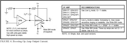
Thsi is what the data sheet says:
"Most general-purpose or precision op amps remain unitygain
stable with the BUF634 connected inside the feedback
loop as shown. Large capacitive loads may require the
BUF634 to be connected for wide bandwidth for stable
operation. High speed or fast-settling op amps generally
require the wide bandwidth mode to remain stable and to
assure good dynamic performance."
The idea is that the buffer is so much faster than the opamp that it does not contribute phase shift, but does buffer th opamp from cap loads, so no series resistor is needed. What IS needed is an input series R of 50-200 ohms for stability. Was that in the circuit? Don't remember. Your turn to check that.
Edit: Don't bother. Neither Alcaid's nor P-A's schematic show the series input R. They must love to live dangerously...
So the circuit looks like PMA's? At the bottom the schematic says "P-A Sjostrom". Funny...
Jan Didden
janneman said:
Christer,
Thsi is what the data sheet says:
"Most general-purpose or precision op amps remain unitygain
stable with the BUF634 connected inside the feedback
loop as shown. Large capacitive loads may require the
BUF634 to be connected for wide bandwidth for stable
operation. High speed or fast-settling op amps generally
require the wide bandwidth mode to remain stable and to
assure good dynamic performance."
The idea is that the buffer is so much faster than the opamp that it does not contribute phase shift, but does buffer th opamp from cap loads, so no series resistor is needed. What IS needed is an input series R of 50-200 ohms for stability. Was that in the circuit? Don't remember. Your turn to check that.
Edit: Don't bother. Neither Alcaid's nor P-A's schematic show the series input R. They must love to live dangerously...
Well, as I said, I was referring to Jungs recommendation
regarding discrete diamond buffers, and he recommends a
series resistor at the output. I wasn't sure what the BUF634
datasheet had to say, but I checked it now, and I think you
missed this sentence: "Response with some loads (especially
capacitive) can be improved with a resistor of 10 Ohm to
150 Ohm in series with the output."
So the circuit looks like PMA's? At the bottom the schematic says "P-A Sjostrom". Funny...
I was referring to this schematic,
http://www.diyaudio.com/forums/showthread.php?postid=401952#post401952
which has no info about
who did it. Maybe it is just that somebody used the same
schematic drawing program as PMA and did a similar circuit?
It is more or less a standard circuit.
janneman said:
...
The idea is that the buffer is so much faster than the opamp that it does not contribute phase shift, but does buffer th opamp from cap loads, so no series resistor is needed. What IS needed is an input series R of 50-200 ohms for stability. Was that in the circuit? Don't remember. Your turn to check that.
Edit: Don't bother. Neither Alcaid's nor P-A's schematic show the series input R. They must love to live dangerously...
...
Jan Didden
Don't see a series resistor on the buffer input in this schematic:
Attachments
Christer said:
...
I was referring to this schematic,
http://www.diyaudio.com/forums/showthread.php?postid=401952#post401952
which has no info about
who did it. Maybe it is just that somebody used the same
schematic drawing program as PMA and did a similar circuit?
It is more or less a standard circuit.
It is almost straight from the datasheet, but I first saw it when I found the schematic by PMA. I've drawn it myself in Eagle though.
The reason I am asking…peranders said:My diamond buffer had less than 0.008% so I'll gather that BUF634 has less than 0.1%, probably less than 0.01%. The datasheet says nothing about this.
It is strange when datasheet of 10 pages does not show harmonic distortion performance. As a rule, it does not happen accidentally.
I know very well the potential of a diamond buffer but I have discovered the monolithic implementations might fail to achieve it. Figures for LH0002 (0.1%) and for the output stage of OPA660 (68dB) are poor for what a diamond can do (though for the first the performance is given at 5V RMS and for the second at 10MHz).

Pedja
Alcaid said:
Don't see a series resistor on the buffer input in this schematic:
It is only mentioned in the text. Neither the inpur resistor
nor the output one appears in any figures, only in the text.
Alcaid said:
It is almost straight from the datasheet, but I first saw it when I found the schematic by PMA. I've drawn it myself in Eagle though.
Yes, it is a very standard circuit. What made me think of PMA's
schematic was the combination of the style of the schematic,
obviously Eagle then, and the, in my opinion, bad symbol for
the buffer. I like buffers to look like single-input op amps
for clarity, but I guess this is the standard in the Eagle
library then.
Christer said:
Yes, it is a very standard circuit. What made me think of PMA's
schematic was the combination of the style of the schematic,
obviously Eagle then, and the, in my opinion, bad symbol for
the buffer. I like buffers to look like single-input op amps
for clarity, but I guess this is the standard in the Eagle
library then.
Yes, it is the standard symbol in Eagle, but I had to make a new footprint though, because the one in Eagle hasn't got space between the pads.
Those who have buildt a preamp with this schematic haven't used an input resistor on the buffer, and they haven't had any problems.
Alcaid said:
Those who have buildt a preamp with this schematic haven't used an input resistor on the buffer, and they haven't had any problems.
It probably won't cause you problems in most cases, but the
datasheet says it can improve performance. Note that most
of the frequency and phase response plots are with a 50 Ohm
source resistance. I agree it is somewhat strange that they
say this when there already is a 200 Ohm resistor at the
input, but probably they keep that resistor somewhat low
in value to allow for further fine tuning. Or maybe there is
some other reason?
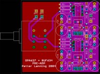
Alcaid said:Some updates:
Groundplane like peranders showed.
Polygons for V+ and V- on signal side of PCB.
Any comments on this?
Turn the noble 90 degrees and leave space at the back:
you (or anyone using the pcb) can use a motorized one then.
Greetings,
guido said:
Turn the noble 90 degrees and leave space at the back:
you (or anyone using the pcb) can use a motorized one then.
Greetings,
That's a good idea, but I don't intend to use a motorized pot. The way it is set up now, it fits my needs perfectly. I'll put the preamp pcb at the back in my cabinet and extend the shaft of the pot to the front. Voila! Short interconnections between the PCB, the RCAs and the source selector.
Christer said:Alcaid,
I just saw another thing. you may wish to add capacitors in
parallel w. R2 and R12 to filter out RFi at the inputs.
Thanks for the tip. What value would you suggest? Don't think I will implement it though because of space constraints.
- Status
- This old topic is closed. If you want to reopen this topic, contact a moderator using the "Report Post" button.
- Home
- Amplifiers
- Solid State
- OPA627 + BUF634 Preamp PCB Design