Hi Eva,
Your point about dropping one 'half' of the LTP in a CFA to "eliminate" phase shift from IN- is a very significant step for audio power amplifiers.
There was a thread using a "Singelton" input stage by Bigun (with an ingenious temperature compensation idea for the single input transistor) and says, "The Singleton can be easier to stabilize, so Cdom can be smaller and slew rate is higher."
Samuel Groner looked also looked at this and had some suggestions for a new form of output stage see - http://www.nanovolt.ch/resources/power_amplifiers/pdf/audio_power_amp_design_comments.pdf
Thanks for the enlightenment initiative.
I was not up to date about those balanced current amplifier low voltage chips with Ghz GBW.
Doing a web search for "diamond buffer" can provide some inspiration for input stages, apart from the sources provided. Note that not all circuits coming out of a web search are optimum. Note that there are some obvious conventions related to drawing circuits in the way the least visual abstraction effort is needed for understanding.
diamond buffer - Bing
Of course a diamond buffer with JFET could not achieve a proper low impedance output, so JFET are mostly restricted to LTP in audio (and more precisely, a LTP driving another LTP).
The real challenge is still the THD/part-count ratio. This involves weighting the THD contribution of each part or configuration.
Another usual confusion is related to local degeneration, cascoding or buffering. Local degeneration, cascoding or buffering shall be aimed to optimize GBW of the whole circuit by controlling local roll-off of each stage. Global GBW will optimize THD. Reason: (except for crossover distortions) linearization due to local feedback is equivalent to linearization due to global feedback (but local NFB when not demanded by GBW constraints usually requires more parts).
And yet, another usual confusion comes when miller compensation capacitors are driven with the voltage drop across b-e of power devices in series. The linearization this type of feedback can provide is inherently limited, as Ic is proportional to the logarithm of Vbe, so past a certain point of optimization, no modification to part types or values can improve THD, only a topology change can. But there are not infinite topologies either, so sometimes an application field can be considered mastered, and a design can be considered an universal entity.
Last edited:
Hi Eva,I meant THD*part-count product.
For THD: >20dB below speaker driver THD (or <0.01%) is already a good point to consider the task completed. But less THD can be obtained from the same part-count. But there is a theoretical THD limit for each possible case of part-count.
Here is the link www.diyaudio.com/forums/solid-state/317335-oitpc-output-inclusive-tpc-tmc.html to thread with a kind of unique type of compensation, at least I never seen similar.
I have built three different amps with this compensation, and I would appreciate you comment.
Damir
I meant THD*part-count product.
For THD: >20dB below speaker driver THD (or <0.01%) is already a good point to consider the task completed. But less THD can be obtained from the same part-count. But there is a theoretical THD limit for each possible case of part-count.
What attracted me to this thread was the title since problems of oscillation are fairly common.
Although this purported to gather information on solutions, a tutorial of sorts perhaps, the dominant theme has been about fixes to a particular genre of circuit.
That can be helped by having done study into the workings of transistors and circuits - too many people skip the 101 stuff and go straight to SPICE - or rely on the knowledge of others when the information is freely available if they would only look.
Knowingly I am not attracted to complex circuits with a high transistor count but there was nothing else of interest around at the time and someone had taken the trouble to do a simulation.
Thanks for that asc file. I downloaded it and hope to give it a look-see. I mentioned earlier though that I have gone over to class D because of oscillation problems with linear approaches. That was definitely an early-on motivation for my change of focus.
Yet, I especially came here today to mention something that I mentioned to you another time that I now wanted to correct. I had said that the class D I was working on had an output impedance in the low to mid tens of milliohms, when I now estimate it 1/10 that earlier estimate. That means when I thought it was 50mOhm, it was really 5mOhm.
Yet, I especially came here today to mention something that I mentioned to you another time that I now wanted to correct. I had said that the class D I was working on had an output impedance in the low to mid tens of milliohms, when I now estimate it 1/10 that earlier estimate. That means when I thought it was 50mOhm, it was really 5mOhm.
Intent is to make working this CFA schematic without oscillations, preferably with balanced input
I tried the the circuit on LTspice and was impressed, although I didn't get insights about stabilizing it. I think I will try inputting a square wave because the output of the 1kHz sine wave was very clean. Maybe a square wave would tickle any instability that might be present.
ItThe 1kHz square wave output was clean. The input square wave had the same amplitude as the sine wave that was already in the circuit when I first opened it (1.2V). With the square it had a rise and fall time of about 400ns, and looked good.
Although, come to remember it, at first my square wave had rise and fall times of 10us before I lowered them to 10ns. Then I did see some ringing during the falling transition period. I also observed about a 300ns crossover period in the middle of that fall period.
Although, come to remember it, at first my square wave had rise and fall times of 10us before I lowered them to 10ns. Then I did see some ringing during the falling transition period. I also observed about a 300ns crossover period in the middle of that fall period.
Last edited:
HTML:
I tried the the circuit on LTspice and was impressed, although I didn't get insights about stabilizing it. I think I will try inputting a square wave because the output of the 1kHz sine wave was very clean. Maybe a square wave would tickle any instability that might be present.
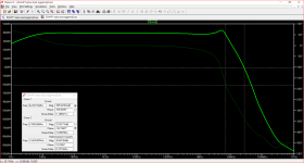
A Bode plot shows this latest circuit to be seriously unstable. At the frequency where phase reaches -180 degrees gain attenuation is practically nil.
Attachments
Last edited:
A Bode plot shows this latest circuit to be seriously unstable. At the frequency where phase reaches -180 degrees gain attenuation is practically nil.
I forgot to say this is representative of the circuit with an 8R test load - albeit this was missing in what we have been given to work with.
MOSFET drivers would go with class D topology. I get an impression of what Eva was saying, though I haven't a suggestion to give for doing it.
MOSFET drivers would go with class D topology. I get an impression of what Eva was saying, though I haven't a suggestion to give for doing it, except basically take the the two input sources and replace them with a single one, plus end to one transistor base and minus end to the other.
- Status
- This old topic is closed. If you want to reopen this topic, contact a moderator using the "Report Post" button.
- Home
- Amplifiers
- Solid State
- One of the Top Solid-State CFA amp design