I think the Thermisters are going bad. the amp has 4 amps of constant current drawn when in use and the thermisters are pretty small so i wonder if they haven't shifted to a lower resistance when cold.I measure about 10-11ohms which isn't much.
20 ohms total to start maybe too low. I may need to go back to 40-50 ohms total and let the first cycle come up even slower. then the rest of the string should be ok at 1 second intervals.
I don't know. I am about to shelve the whole thing.
Zc
20 ohms total to start maybe too low. I may need to go back to 40-50 ohms total and let the first cycle come up even slower. then the rest of the string should be ok at 1 second intervals.
I don't know. I am about to shelve the whole thing.
Zc
Thanks for the suggestions. I AM going to try that bias trick. and yes I use these with a large set of Duntech speakers so low low bass is good! and I actually thought of trying to find a way to slow the onset of bias at first start up when I first guessed at what was going on but wasn't sure how to accomplish it!
I'm just frustrated at the moment! these amps ran fine for months!
I'm just frustrated at the moment! these amps ran fine for months!
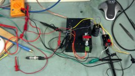
I mocked up a quick ZL on a spare heatsink to do some experimenting with. My bench supply wont quite supply enough current or voltage But enough to make the mocked up version run. I noticed that with the input shorted. the output cap holds the D-S voltage at about 5V once the amp is shut off. I experimented with a 10K resistor across the mosfet which slowly drains the output cap down after power off. I have no idea what effect that resistor would have in normal use??
I also experimented with shorting the input and shorting the output and leaving it shorted well after the amp powered up and nothing I did on the bench caused a mosfet failure!
Tomorrow I will experiment using the supply in one of the ZL's to power the mocked up version and see what happens.
This way I don't have to muck up the insides of Papas ZL's until I have an idea of whats going on. Plus is was fun to build.
Attachments
Well I learned some things tonight with the bench Zen and well lost another half dozen mosfets. But I think I'm on to something.
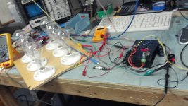
With the Bench Zen here in referred to as the BZ, connected to the ZL power supply, I had the exact same problems! So I built up a simple new power supply and guess what? same exact problem no change! Now remember the BZ is built from entirely new components and I'm still having failures! SO...zoom out and look at the bigger picture. what is common to both scenarios? wait for it......INPUT SHORTING Tadaaaaaa! In all my tests I had the input shorted. My preamp shorts the output, hence the ZL input when in mute! Un short the input and I can flip on the BZ from a cold start no issues and no dead mosfets! In fact I flipped i did it a dozen times and not one failure!
But I also learned that If I short the input, flip it on and blow a mosfet, change the mosfet and unshort the input that I would have to bring it up on the variac or the mosfet would just blow again. but If i brought it up on the variac and let it run for a bit. then flip it off, let it cool down i could flip it on at random without a failure!
So this confuses me. If the input is shorted and the input cap is discharged. that should hold the gate closer to ground until the cap can charge up through the 56.2K resistor. so what in the heck is going on?
I don't have any definitive answers yet and I'm down to 3 mosfets left so...Anyone have any ideas?
Zc
I have not added gate stoppers just yet, But I was watching the gate with a scope and saw no obvious signs of oscillation! I was trying to capture the gate rise to see if it was exceeding 20V but I just don't think my scope can catch that. I have it set on a very slow sweep to try and capture any sort of spike and I don't see anything above 4-5v at worst case. I have a digital scope that might be able to capture it better if I can figure out how to do it.
I have ordered another tube of mosfets. they wont be here for a week so I will probably play with it for a bit today until the last of the mosfets die then shelve it for a while.
Zc
I have ordered another tube of mosfets. they wont be here for a week so I will probably play with it for a bit today until the last of the mosfets die then shelve it for a while.
Zc
Ok we are gettin somewhere! I added a 150 ohm gate resistor right at the mosfet and with the bench supply made up of a transformer a bridge and a 10kuf cap no more blown mosfets! BUT connect up the ZL supply and blammo dead mosfet!
SO, i am trying the network as suggested made up of a 9.1K and 47K resistor with a 47uf cap to ground in place of r2. should i put the 47K on top connected to the + supply? or the 9.1K on top??
SO, i am trying the network as suggested made up of a 9.1K and 47K resistor with a 47uf cap to ground in place of r2. should i put the 47K on top connected to the + supply? or the 9.1K on top??
Last edited:
9.1K on top, 47K to mosfet, cap in between to ground, but the fact that the mosfet blew anyway probably indicates there is more going on here. I'd check the SOA rating of that mosfet both dc and over a 10msec and 100msec interval and make sure you are not exceeding it. Are you sure that initially you are not exceeding the rated Vds of these mosfets?
Had a recent interesting SOA problem with a mosfet based inrush suppression circuit, turns out that the original design grossly exceeded SOA during the first 100msec of operation. (Voltage across the device combined with the initial current through it, oddly enough this was a 120A rated, 150W part, but the SOA allowed no more than a few hundred mA with >25V across it, and at a Vds of 1V 100A or more was OK) So check that something hasn't changed causing you to exceed some device maximum rating. (Higher average line voltage, etc..)
Had a recent interesting SOA problem with a mosfet based inrush suppression circuit, turns out that the original design grossly exceeded SOA during the first 100msec of operation. (Voltage across the device combined with the initial current through it, oddly enough this was a 120A rated, 150W part, but the SOA allowed no more than a few hundred mA with >25V across it, and at a Vds of 1V 100A or more was OK) So check that something hasn't changed causing you to exceed some device maximum rating. (Higher average line voltage, etc..)
Well the supply is 55v no load and about 45v under load. the 044 mosfets are 55v parts but I also have 140 mosfets that are 100V parts and they blow too!
BUT, if I lower the variac so that the supply is at about 35v under load. they seem to survive. so maybe the CLC in the ZL supply is causing a spike at turn on?
Zc
BUT, if I lower the variac so that the supply is at about 35v under load. they seem to survive. so maybe the CLC in the ZL supply is causing a spike at turn on?
Zc
It is quite possible, the 55V parts probably would not survive under high line conditions, but the 100V parts should provided that their SOA is not exceeded during power up. One of the things I would investigate would be whether or not the CLC rings when the FET actually starts to turn on.. Should such be the case a snubber across the inductor might or might not help, a small resistance in series with the choke might help too by lowering the effective Q of the inductor.
Might be worth simulating the supply in PSUDII..
Might be worth simulating the supply in PSUDII..
Are the broken devices shorted from drain to gate?
The maximum voltage stress from drain to gate is no more than 20 volts (per data sheet). Actual devices would probably not breakdown until stress reached > 30 volts, but probably < 55 volts.
With input shorted to ground, initial voltage stress from drain to gate is 55 volts. When input is not shorted to ground, initial voltage stress drain to gate is 40 volts.
You were close when you used zener to limit voltage, but you needed to limit drain to gate voltage, not gate to source voltage.
One solution while shorting input, is to use 27v zener drain to gate.
Another solution is to place resistor in series with gate. Not 100 ohms, but more like 20K ohms.
Did this help?
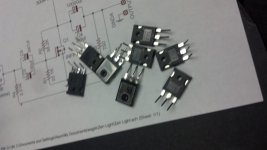
All the dead devices are shorted all three legs together! everything shorted! just dead..plain dead!
AHHHH Drain to gate Zener the one thing I didn't try. When the new tube of mosfets get here I will try that and see how it goes. I did notice with the 150 ohm gate resistor that on switch flip power up with the bench supply that it was more stable. less bouncing around. the D-S voltage would always do this sort of slow wave before settling in and with 150 ohms at the gate it would just snap right in and be stable right away. But the ZL supply does this very fast bounce which I think is the 2nd bank of caps charging through the slow inductor. which a better soft start system will help once i get this other issue fixed.
20K gate resistor? I have never seen a gate resistor that high in any amp before. 1K in some ampeg bass amps is as high as i have ever seen. normally i see low values, 47ohm to 150ohm. I'm willing to try 20K but will that affect operation? with 2000pf of gate capacitance will 20K affect HF perf??
Thank you for the help also!
Zc
Your failure mode is gate oxide rupture (blown). Short from gate to drain will also measure as gate to source and as gate to substrate. Too much voltage at turn-on from drain to gate. It only takes < 100 nanoseconds for gate oxide to breakdown. This occurs at ramp-up of power supply voltage. When you slowed power supply ramp up, input capacitors (C2 & C5) starting charging from 0v towards 15 volts. As gate charged, drain to gate voltage stress stayed under breakdown voltage.
There is no practical way to measure breakdown voltage without actually breaking down the oxide, which does not recover. However, measurement of one device from a tube will be indicative of other devices in tube. In my experience, we always allowed a 50% margin, but usually less than 100%.
The lower the gain of the device, the thicker the oxide and thus, the higher the breakdown voltage.
The theory of the high gate resister - actual gate will be isolated from 100uF input capacitor, which is initially discharged, by the high gate resistance. Internal 1000pF gate to drain capacitance will charge internal 1000pF gate to source capacitance to ~ 1/2 of drain to source voltage. Of course, as gate voltage goes up, device turns on, reducing drain to source voltage, current starts flowing and power supply voltage goes lower.
Is 20K too high? - 20K and input capacitance of 2000pF (plus internal miller capacitance of ~6 x 1000pF) will limit high frequency response.
Have I made you an expert on MOS devices yet?
- Status
- This old topic is closed. If you want to reopen this topic, contact a moderator using the "Report Post" button.
- Home
- Amplifiers
- Pass Labs
- One of my Zen Lights has died!