OK, how is that normally measured? I can direct high SPL at the tube, but we need to know how much is coming from the vibration of the chassis by sound and how much from the tube envelope and base alone. How to isolate those two effects?It would be interesting to know if its necessary to try to protect the tubes from soundwaves also.
Hang the tube by coiled wires? Vibrate the base alone?
You just have to do the maths for the typical operating point of the DHT in question. Look at the filament voltage, current and the bias. That gives you the cathode resistor and the DC filament required for the regulator (add 5v).
26 - 1.5v - 1A - 10v = 10 ohms (20W) DC required 10+1.5+5 = 16.5v
300b - 5v - 1.3A - 70v = 54 ohms (150W) DC required 70+5+5 = 80v
See what I mean? 300b as an output in filament bias needs a 150VA transformer just for one tube! The 54 ohm cathode resistor is 150W. And all this assumes you can make a filament regulator that works at 70v which is no joke.
There are other ways of using 2a3 and 300b but the usual kind of filament bias that suits the 26 and 4P1L isn't really an option.
Same as RCA not?
Thanks for the offer but I don't think it will be worth the trouble you have to go through.
Seems like 4P1L as input is too much trouble to bother, it’s a pity as it simulates better than the 26 but that could well be the spice model I use. Besides so many good reports about the 26 that I can’t really go wrong there.
The 26 as input starts clipping at about 1.8Vrms input in the simulation is that about right in real life? It does not really matter as max power of the amp will be reached at about 1.3Vrms with 1:1 interstage.
Yes is RCA re-branded Cunningham.
My 26 don't clip with an input of 2Vrms
")
Did you measured it?My 26 don't have any kind of suspension, zero microphonics (less of 1mm mobil telephone near the tube), zero hum, only superb music....
These tubes are old as Queen Elizabeth II, and their parameters changed in the course of the storage.
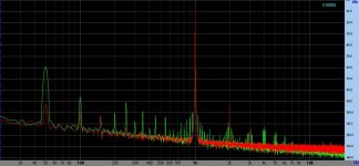
One of them soundproof, others are not humming audibly, but produce horrible (50 or 60 Hz and overtones) sidebands about the carriers. This appears in the sound unfortunately. :-(
The difference between two tubes sometimes 30dB at 50Hz!
But all of them microphonics, more or less.
Attachement: one of my Majestic #26 pair spectrum (filament bias, R. Coleman reg., 7V RMS out).
Attachments
I'm curious to know what parameters were used that led to the sim result of a 26 clipping with 1.8Vrms in. (operating point, load, wind speed, etc.)
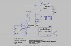
Operating point 132Vpk @ 4.2mA (clipping starts at 1.6Vrms)
Interstage 1:1 150H DCR 600ohm
Load resistor 1st stage is RLoad1 in distortion simulation.
Wind SW 5bft swell SW 4m (Indian Ocean Sunday 0300 arrival pilot station Mumbai
 )
)See attached circuit and distortion simulation.
Attachments
Spice model used for the 26
.subckt 26 P G K
Cgp G P 8.1p
Ci G K 2.8p
Co P K 2.5p
* Modified Koren model (8 parameters): mean fit error 0.0885651 mA
Gp P K VALUE={(0.01442887772m)*limit(V(P,K)*log(1.0+(0.1253141833)+exp((11.02662544)+(11.02662544)*((7.991655127)+(-5.673592559m)*V(G,K))*V(G,K)/sqrt((27.79481263)**2+(V(P,K)-(5.150763388))**2)))/(11.02662544),0.0,1.0e16)**(1.440761354)}
.ends 26
This is perfect in LTSpice:
* 26 - DH power amplifier low-mu Bp P K I=(m)*uramp(()*V(G,K)+V(P,K))**1.5 (filament: AC/DC 1.5V 1.05A)
* From RCA 26 datasheet - traced on 28-11-01 by AF
.subckt 26 P G K
Cgp G P 8.1p
Ci G K 2.8p
Co P K 2.5p
* Modified Koren model (8 parameters): mean fit error 0.0885651 mA
Bp P K I=(0.01442887772m)*uramp(V(P,K)*ln(1.0+(0.1253141833)+exp((11.02662544)+(11.02662544)*((7.991655127)+(-5.673592559m)*V(G,K))*V(G,K)/sqrt((27.79481263)**2+(V(P,K)-(5.150763388))**2)))/(11.02662544))**(1.440761354)
.ends 26
At 3V peak input produce 22.9V peak output and 0.063% THD (-64dB H2, -83dB H3).
-------------------
Instead of this, I use Dmitry Nizhegorodov's composite library for heater bias circuits.
Attachments
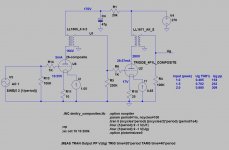
Tried Dmitry's model, same problem. With 2nd stage disconnected I got the same results as euro21. As it turns out the 4P1L started drawing grid current at around 1.7Vrms input on the 26. Never noticed this with two 4P1L's as a 4P1L in the 1st stage can deliver the needed grid current I think.
So I upped the 4P1L anode voltage to 264V @ 29mA. Now clipping occurs after about 2.8Vp input.
So I upped the 4P1L anode voltage to 264V @ 29mA. Now clipping occurs after about 2.8Vp input.
Attachments
Right. The actual word and mechanism why this is so it's where the debate is. I think the consensus is that paralleling two tubes only sometimes sound better than one. I have to say I haven't played with this at all. Got a whole bunch of 4P1L for this but... so little time. I'm also curious of a 4P1L PP.
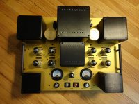
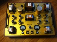
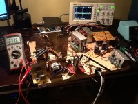
Sorry to interfere in a SE thread. Just browsing through and wanted to satisfy Iko's curiosity. Here is my PP amp with Lundahl transformers. Amazing sound. I am playing now building a PSE 4P1L and can tell that Andy Evans described about the sound is so true. I can't stop listening to piano and jazz.Here is my PP and a picture of PSE breadboard.
Attachments
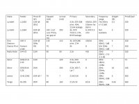
I am trying to imagine the best scenario for the OT of a PSE 4P1L amplifier. From different plate characteristics posted on the web (old and new), and an optimal operating point of 250V, 35mA, -21V one can calculate the Rp(Ra) of 4P1L. IT varies between 1200 and 1400ohm. I would say that an optimal primary OT for PSE 4P1L would be 2.5-2.8Kohm. I opted to look rather at a 3K trafo than a 2.5k. After measuring my tubes most of their Rp is somewhere between 1400-1500ohm (at the operating point shown above). Here are my findings:
Make Model Pmax SE (W) Gapped (mA) Iprmax (mA) Primary Secondary Frequency range Weight (lB) Price$/pair
Lundahl LL1620 13W @ 30hZ 80 3.3k, DCR 308 ohm, 45H, 11mH leakage 4/8/16, DCR 0.8ohm for 8ohm 7hz-25khz +/- 0.5dB 5.5 520
Lundahl LL1664 10W @ 30hZ 100 ( not sure if they can gap at 70) 200 3k, DCR 72ohm, 17H, 8mH leakage 8, DRC 0.5 ohm Not available 3 320
One Electron UBT-3 15W @ 50Hz 110 110 3k, DCR 286 ohm, 17H 4/8/16 20hZ-40khZ, -1dB 5 220
Electra Print Custom order 5W 70 3k 8 Min 25Hz-20khZ, -1dB ? 350
Audio Note 144-V2 15W 90 90 2.5k 4/8 20hZ-20khZ, -1 to -1.5 dB ? 230
Edcor GXSE15-6-2.5K 15W ? 120 2.5k, DCR 95ohm, 6H 6 40hZ-18khZ, <1dBu ? 75
Edcor CXSE25-8-3.2K 25W 200 3.2K, DCR ?, Lpr ? 8 20hZ-20kHz, <1dBu 10 166
James JS-6112HS 10W @ ? 70 ? 2.5K/3.5K 8 29Hz-50kHz, -2dB 3 300
Tango XE-20S 20W 80 160 2.5/3.5K 8/16 25Hz-90kHz, -2dB 4.66 660
As always compromises have to be considered. In order to balance price and sound quality balanced with all the components, schematic (so we are not creating a weak link), I would consider LL1664 (if they would gap for 70mA), Electra Print and One Electron UBT-3. Also Audio Note can be considered as it has good reviews.
I am experimenting now with a UBT-1 that I had available. I started with a quad 4P1L that is appropriate for the UBT-1 (1.6K/4, 8, 16). To implement filament bias at 21V and 2.5A is too challenging from a heat management point of view. Despite that I would like to see a quad 4P1L, I had to go for a PSE 4P1L where the filament bias will dissipate acceptable levels of power on Rf (21V*1.37A=28.77W) to achieve the desired sound.
If you are interested in building this amp, I am sure that the challenge of choosing the best fit OT came to your attention.
What is your best fit and experience?
Best Regards,
Radu
I use the O-netics "commercial" model which is great for 2 x 4P1L in PSE. You should add that one. It has less bass but better treble and overall sound than the Audionote Trans-152 which is massive and 2.5K. I have a LL1620/80mA which I haven't heard with PSE 4P1L. With 300b it sounded roughly equal to the Trans-152, maybe a tad better. Not as good as O-netics.
You need 70mA capability - maybe 80-90mA like the O-netics or Trans-152. The O-netics is physically small and not designed for more than 300v, so 250v is nice.
I've thought about 3 x 4P1L at 30ma each into the Trans-152, upping the p-k voltage a little. I'm not hugely tempted, but it wouldn't be a problem in filament bias. You absolutely have to run these outputs in filament bias if you want the good sound.
- Home
- Amplifiers
- Tubes / Valves
- One more 4P1L SE