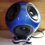
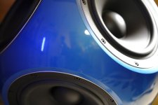
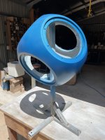
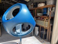
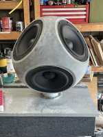
Hi Ho, just finished my 3d Printed Sub build. I have plenty of construction photos if anyone is interested. Sub features 6 x 10in drivers from SB Acoustics. Its fully 3d printed with epoxy filled walls and with an internal force cancelling structure to link all the drivers. Its completely force cancelling in all directions and is a sealed design.
Best wishes,
Ben.
Best wishes,
Ben.
Attachments

Last edited by a moderator:
Using 3D printing for the enclosure with epoxy-filled walls is a unique approach, and having a force-canceling structure with six 10-inch SB Acoustics drivers sounds very ambitious.Hi Ho, just finished my 3d Printed Sub build. I have plenty of construction photos if anyone is interested. Sub features 6 x 10in drivers from SB Acoustics. Its fully 3d printed with epoxy filled walls and with an internal force cancelling structure to link all the drivers. Its completely force cancelling in all directions and is a sealed design.
Best wishes,
Ben.
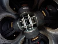
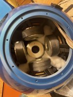
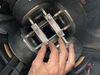
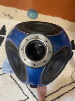
…it was a little ambitious, in the end I only linked 4 of the six drivers, I can do all six but it required making a specialised tool to complete the assembly and I had lost a little momentum by that stage. That said you can’t feel any vibration in the cabinet at all when it’s running, you could literally hang it from a wire and it wouldn’t move at all. Here are some pics of the insides. Epoxy works well as does polyurethane resin to fill the wall cavity. In the past for full range and multi driver designs I have also used polyurethane rubber to control ‘panel’ resonance.
Attachments
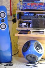
Hi there, the sub and the main speaker (photo in original post) myself. Both were printed on a Formbot Raptor with a build volume of 400x400x700. This was a very affordable large volume printer when I bought it in 2018ish. I now have the Ratrig 500x500x500 which is a way better printer but costs a lot more, it is available as a kit in Aus. Hope this helps. Am selling the Formbot Raptor if you are interested.
Wonderful implementation. I'd love to see your build photos!I have plenty of construction photos if anyone is interested.
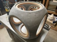
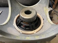
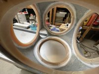
Here are the remaining photos of the construction. The images show the raw shell out of the 3d printer, it has had minimal filling in the first stage to make it water tight and able to hold the epoxy when the wall cavity is filled.
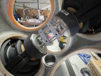
It was printed in two halves. You can also see some beige rings being used to attach the drivers. These were rough cast out of polyurethane resin and machined to fit the shell. They were tapped to accept a M6 bolt rather than screw to attach the drivers.
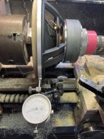
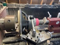
The drivers were a little oversized and not quite round. This is no fault of the manufacturer as cast frames will never be accurate until they are machined. You can see me machining the drivers on the lathe to get them round and to correct size. This seems daunting at first but isn’t too bad reality.
It was printed in two halves. You can also see some beige rings being used to attach the drivers. These were rough cast out of polyurethane resin and machined to fit the shell. They were tapped to accept a M6 bolt rather than screw to attach the drivers.
The drivers were a little oversized and not quite round. This is no fault of the manufacturer as cast frames will never be accurate until they are machined. You can see me machining the drivers on the lathe to get them round and to correct size. This seems daunting at first but isn’t too bad reality.
Attachments
Last edited:
… sorry ran out of time to edit in the last post, here are the remaining pictures and description…
Here are the remaining photos of the construction. The images show the raw shell out of the 3d printer, it has had minimal filling in the first stage to make it water tight and able to hold the epoxy when the wall cavity is filled.
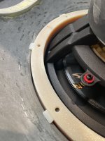
It was printed in two halves. You can also see some beige rings being used to attach the drivers. These were rough cast out of polyurethane resin and machined to fit the shell. They were tapped to accept a M6 bolt rather than using screws to attach the drivers.
The drivers were a little oversized and not quite round. This is no fault of the manufacturer as cast frames will never be accurate until they are machined. You can see me machining the drivers on the lathe to get them round and to correct size. This seems daunting at first but isn’t too bad in reality. I also wanted the aluminium edge to show so it matched the design of my mains.
Hope this helps, there is more detail on the construction in a post I made about my mains a few years ago, I will attach the link here.
https://www.diyaudio.com/community/threads/new-markaudio-drivers.324962/page-82
Here are the remaining photos of the construction. The images show the raw shell out of the 3d printer, it has had minimal filling in the first stage to make it water tight and able to hold the epoxy when the wall cavity is filled.
It was printed in two halves. You can also see some beige rings being used to attach the drivers. These were rough cast out of polyurethane resin and machined to fit the shell. They were tapped to accept a M6 bolt rather than using screws to attach the drivers.
The drivers were a little oversized and not quite round. This is no fault of the manufacturer as cast frames will never be accurate until they are machined. You can see me machining the drivers on the lathe to get them round and to correct size. This seems daunting at first but isn’t too bad in reality. I also wanted the aluminium edge to show so it matched the design of my mains.
Hope this helps, there is more detail on the construction in a post I made about my mains a few years ago, I will attach the link here.
https://www.diyaudio.com/community/threads/new-markaudio-drivers.324962/page-82
Attachments
- Home
- Loudspeakers
- Subwoofers
- "Omni" Sub 3d Printed