Salas is very smart design, but IMO thanks to Depletion mode mosfet it can be simplified. If you don't have Depletion mode mosfet available you may stick to Salas but IMO 13 components around Q1 can be replaced by only 2: one DN2540 and one resistor.
I can see a point of failure in the design: Q4. If Q3 fails to shunt then Q4 boom!
Below is a simplified version of similar concept of Salas function PSU with 1/3 of components and no low voltage floating devices
The depletion has been tried in the ccs. Handy, but subjectively disliked. About simplification and OD stabilizers comparison read http://www.diyaudio.com/forums/tubes-valves/151421-26-pre-amp-39.html#post2142080 If Q3 will not shunt current, the jfet is still nested in the MJE's Vbe. What will make it see more than its 40V max Vds across? Current regulation will just suffer, in such a scenario. What can fail is Q1 if you short a Vout over 200V and you don't use a 150V Zener across Q1. OTOH If someone is about shorting high voltage here and then, better avoid tubes and try with op amps, would be a safer angle. Some components around it are extra in that schematic BTW. 3 Leds resistors instead of one at 5W and the optional Zeners. No big deal if there is a pcb IMHO.
The depletion has been tried in the ccs. Handy, but subjectively disliked. About simplification and OD stabilizers comparison read http://www.diyaudio.com/forums/tubes-valves/151421-26-pre-amp-39.html#post2142080 If Q3 will not shunt current, the jfet is still nested in the MJE's Vbe. What will make it see more than its 40V max Vds across? Current regulation will just suffer, in such a scenario. What can fail is Q1 if you short a Vout over 200V and you don't use a 150V Zener across Q1. OTOH If someone is about shorting high voltage here and then, better avoid tubes and try with op amps, would be a safer angle. Some components around it are extra in that schematic BTW. 3 Leds resistors instead of one at 5W and the optional Zeners. No big deal if there is a pcb IMHO.
Thanks for your information.
A part the simplicity of using depletion mode mosfet for ccs instead of Q1 and involved parts what would be the difference in performance?
No doubt the shunt section is a beauty and I cannot express for now any comment for tube VR vs mosfet shunt. I hope to try soon with this project.
My previous comment was about simplicity PCBless thing.
I have to say I'm using Salas Shunt on my DAC 2 end and I never seen a power supply performing so well. Very impressive
")
In the near future I want to use your SS for voltage/driver stage of my new 2A3 FDH amplifier. I don't reject solid state in tube design. My goal is always best performance no matter how.
Last edited:
There are trend differences. The 9610 and associated bias scheme give a flat PSRR in most of the audio band. Starts picking slowly after 10kHz. The depletion has good numbers but picks up monotonically from lows. Since with no one we are going to beat the system ground limit for numbers, I just focus on trends. I have a subjective preference to the PMOS enhancement one, but you should try for yourself.
Attachments
There are trend differences. The 9610 and associated bias scheme give a flat PSRR in most of the audio band. Starts picking slowly after 10kHz. The depletion has good numbers but picks up monotonically from lows. Since with no one we are going to beat the system ground limit for numbers, I just focus on trends. I have a subjective preference to the PMOS enhancement one, but you should try for yourself.
At the moment I'm using depletion mode mosfet as anode active load in a single end tube amp as a matter of easy setup and overcoming wide band SE transformer limitations (even though efficiency goes down) but after your post about PSRR I can see the point. I was wondering how to implement enhancement mosfet in this case.
Last edited:
As in SSHV. I think that PMOS is better tone there. In general I have an aversion to actively loading an anode though. For what is worth I find anode constant voltage gyrators preferable to CCS if its a must. Ultimately I prefer chokes. I can understand the cost and bulk implications though. I think that pulling from the cathode actively is better to my ears than shoving in anode. But that is a big discussion and very subjective, belonging to the tubes section.
There are trend differences. The 9610 and associated bias scheme give a flat PSRR in most of the audio band. Starts picking slowly after 10kHz. The depletion has good numbers but picks up monotonically from lows. Since with no one we are going to beat the system ground limit for numbers, I just focus on trends. I have a subjective preference to the PMOS enhancement one, but you should try for yourself.
Simply as matter of discussion and personal understanding:
Under what condition the depletion mosfet was compared to enhancement? What voltage? I kind agree the PSRR chart on low voltage depletion mosfet is not so flat but on high voltage could turn around. For example in the low voltage Salas Shunt for DAC end 2 IMO depletion cannot be as good as enhancement. On SSHV I'm not sure if the preference is still valid, in other words if the depletion still looses the battle.
If depletion mosfet still unlikely maintain the pictured PSRR on high voltage I'm still try to justify the use of enhancement (Q1) in SSHV in constant current section (I'm not talking about the shunt). As most of the high frequency may already be gone to ground through the shunt do I still need to generate so much power dispersion (through 3 x 5W parallel resistors) and noise to avoid a more efficient design with depletion mosfet in the constant current section?
Best regards,
Last edited:
Hi All!
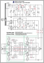
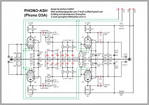
Do you still need PCB of Phono D3A?
design by Andrea of RiiA
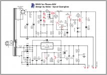
And Salas design Shunt regulator.
All list , you can help me check fix it.
1. apelizzo
2. gioz
3. toufu
4. pred
5. anilva
6. guglielmope x 1
7. wushuliu
8. John Caswell x 2
9. Tangmonster x 2
10. khaho
11. Webby
12. bbe
13. audiodesignguide
14. le´flu x 5
15. vgeorge x1
16. habsrock93 x1
17. eeyore x1
18. Torsken
19. booangler 2
20. vanofmonks 1
21. Loboone x 1
22. Pilsern x2
23. 3GGG x1
24. Presbel x 1
25. Exurbia x 4
Do you still need PCB of Phono D3A?
design by Andrea of RiiA
And Salas design Shunt regulator.
All list , you can help me check fix it.
1. apelizzo
2. gioz
3. toufu
4. pred
5. anilva
6. guglielmope x 1
7. wushuliu
8. John Caswell x 2
9. Tangmonster x 2
10. khaho
11. Webby
12. bbe
13. audiodesignguide
14. le´flu x 5
15. vgeorge x1
16. habsrock93 x1
17. eeyore x1
18. Torsken
19. booangler 2
20. vanofmonks 1
21. Loboone x 1
22. Pilsern x2
23. 3GGG x1
24. Presbel x 1
25. Exurbia x 4
Salas,
In the meantime I will start reading your long thread about the Simplistic HV.
Sorry I did not browse your posts earlier. That is the best you could do, read the thread, many reports of builds there too. As for using the depletion or not, as I told you, nothing beats having your own application there, powering it, and exchanging ccs scheme for checking practicality, oscillation, reliability, subjective influence or not in your own system. You got to make it and see for yourself. Technically its a sound practical solution. No problem. It still shows psrr curve trend difference to PMOS in HV simulation too BTW. Though the numbers at 20kHz are alike. The bias voltage difference and external provision for PMOS must be shaping the regulation differently.
HEATSINK TO-220 for IRF9160 and IRF840
Digi-Key - HS385-ND (Manufacturer - 530001B02500G)
Digi-Key - HS350-ND (Manufacturer - 529802B02500G)
Digi-Key - HS349-ND (Manufacturer - 529801B02500G)
Digi-Key - HS385-ND (Manufacturer - 530001B02500G)
Digi-Key - HS350-ND (Manufacturer - 529802B02500G)
Digi-Key - HS349-ND (Manufacturer - 529801B02500G)
- Home
- More Vendors...
- Quanghao Audio Design
- OLD THREAD Hi-end phono preamplifier by Andrea Ciuffoli