I think it's quite clever.
Since you are using gnfb, have you considered replacing R6 with a CCS to improve PSRR and increase fb factor?
I quite like the cap coupling, because my experience is that if you DC bias these caps, the caps sound much better.
The EF output load R7 would tend to add H2; you might consider a CCS here too.
Hugh
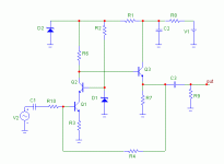
As far a I can see, this circuit would not be able work properly  . DC conditions would be OK only if R4 is very large and that would in turn create potential problems with the feedback arrangement and amp bandwith, rendering R10 useless. It won't be very stable with temperature as well.
Did you try to simulate it?
Cheers
Alex
P.S. - Dont get me wrong - I like this kind of topology a lot and used this extencively in the past. For instance all MM/MC preamps I've done for Creek did use very similar arrangement of transistors - but with no NFB except local, thought.
. DC conditions would be OK only if R4 is very large and that would in turn create potential problems with the feedback arrangement and amp bandwith, rendering R10 useless. It won't be very stable with temperature as well.Did you try to simulate it?
Cheers
Alex
P.S. - Dont get me wrong - I like this kind of topology a lot and used this extencively in the past. For instance all MM/MC preamps I've done for Creek did use very similar arrangement of transistors
- but with no NFB except local, thought.PMA said:Sure, I have all the necessary simulation results
In this case you should be using R4 value of few megs and your circuit DC conditions would vary with temperature and transistor parameters. I am usually trying to avoid this kind of complications. However it is a matter of taste after all
. Cheers
Alex
PMA said:P.S.: the R10 has nothing to do with gain. Gain is set by R6/R3. And R4 is just biasing resistor.
Please accept my apologies. I would probably do it somewhat different (as I did in the past), as I would try to avoid any kind of feedback except local in a circuit like that and in your case R4 would affect things at the bottom end.
Cheers
Alex
x-pro said:
Please accept my apologies.
This is absolutely no problem, Alex. We are having fun here, aren't we?
PMA said:We are having fun here, aren't we?
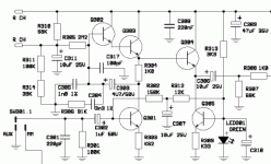
Absolutely. Here is a (rather poor quality, sorry) phono stage circuit I've done for Creek in about 1994 . It was released as OBH-8 stand alone MM preamp and also was used in Cambridge Audio A3i amplifier as well as in many Creek integrated amps as a plug-in.
Cheers
Alex
Attachments
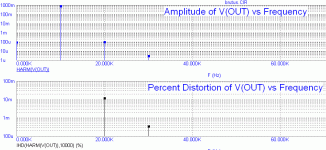
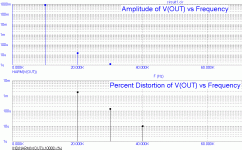
PMA said:Distortion at 1V, 10kHz (simulated).
Yes, 0.01% is possible for a good combination of values
What was the gain in this case?
Cheers
Alex
PMA said:Hi Alex,
The gain was 9 dB.
Regards,
Pavel
Hi Pavel,
here is a result of my simulation with 3 transistors and local NFB only for 9 dB gain and 1V RMS output (somewhat different circuit
)Cheers
Alex
Attachments
PMA said:Hi Alex,
excellent!
(somewhat different circuit, as you have said
P.S.: anyway, your 3rd harm. is higher than mine ...
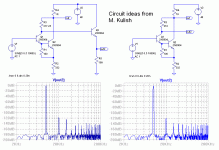
Pavel, in any case we can not compete to the circuit I attach here, by Michael Kulish from Russia. I made two simulations, one with and one without an output follower, both under the same conditions - 10 kHz, 1 V RMS output, 9dB gain. It is an excellent application of an error-correction way of linearization in a very simple circuit. It works in real life too
.Cheers
Alex
Attachments
x-pro said:
Hi Pavel,
here is a result of my simulation with 3 transistors and local NFB only
Cheers
Alex
Hi Alex,
though it is maybe not apparent, as the component values are missing, the circuit I posted had also local NFB only. Gain is completely defined by R6/R3 (with respect to hFE, off course). R10 is very low in value and can be omitted completely. R4 is just biasing resistor and its value is like 10M. Input impedance is quite high (about 1M) and R4/R10 do not constitute global feedback.
Cheers,
Pavel
x-pro said:
Pavel, in any case we can not compete to the circuit I attach here, by Michael Kulish from Russia.
Cheers
Alex
Looks very interesting

x-pro said:
, by Michael Kulish from Russia. I made two simulations, one with and one without an output follower, both under the same conditions - 10 kHz, 1 V RMS output, 9dB gain. It is an excellent application of an error-correction way of linearization in a very simple circuit. It works in real life too
Hi Alex,
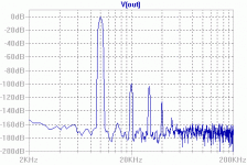
hereby what I got from the Kulish circuit. No follower and no load. Excellent result, however.
P.S.: I have to add that this is for source impedance of 1k. Distortion very quickly rises with Zout of the signal source. This is very very different from my circuit, which yields quite same distortion even for 100k source impedance.
Attachments
anatech said:Hi Alex,
Try to simulate a real world load on your outputs and rerun the sims please. I always find unloaded measurements much more promising than loaded ones. Some circuits are much better than others in this respect.
-Chris
The distortion of this circuit is load-independant without the output buffer, only the gain will change if you connect load (with a coupling capacitor) to the (out2) of the second (unbuffered) circuit.
PMA said:P.S.: I have to add that this is for source impedance of 1k. Distortion very quickly rises with Zout of the signal source. This is very very different from my circuit, which yields quite same distortion even for 100k source impedance.
I've just copied the values from the original article. Transistors here are run with high currents so the input impedance is fairly low. You may increase the resistor values and reduce that effect thought 10K distortion would rise a bit. Also this is an error-correcting circuit and as such requires balancing of the correction - as you may see I had to adjust one of the values to partially compensate for the buffer distortion. In the same way it is (I think) possible to compensate some of the imbalance due to the source impedance if it is constant.
Cheers
Alex
- Status
- This old topic is closed. If you want to reopen this topic, contact a moderator using the "Report Post" button.
- Home
- Source & Line
- Analogue Source
- Old fashioned simple preamp