Is there a way to test old electrytic caps to see if they are good enough to be used? I've read about lives ranging from 10-20 years, but I'm hoping there's a test or two to validate/quantify it.
Charge them with current until the leakage is under 1mA each. It may take an hour, or several.
A power supply of rated voltage and a series resistor to limit the current to less than 100mA or less are needed. For example, a 300V supply and 10k resistor at 10W will do. (The resistor should be large enough in power to deal with a shorted cap.) The voltage across the 10k would be less than 10V when the cap is reformed, as 1mA x 10k = 10V.
Yes, try to reform them as rayma says - although I would use a lower current than 100mA. In many cases this will be sufficient. Otherwise, measure capacitance and ESR and compare with the requirements of the circuit location.
Yes, this is the minimum that you should do. There's no assurance that the caps will be like new after reforming, though. They may have higher ESR than spec.
You can use a larger resistor to reduce the maximum charging current, or a current regulated power supply to control the current directly. In this case, I'd set it to 10mA.
If the charging current stays higher than a few mA, the cap is probably bad.
Also, inspect the vent and terminal areas for signs of leakage. If any exists, discard the cap.
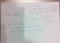
Hello, sorry it's been so long for me to reply. I've attached a schematic of what I think we're taking about. Excuse poor art and handwriting.
I have a 30Vdc (unreg) handy. The cap is 15,000uF max 75Vdc. Max current occurs when cap is shorted, correct? So if i use a 1k resistor, max current is 30mA, max power through resistor is 0.9W. Time constant is 15s, which is short, correct?
How do I correctly measure leakage current? Is it as simple as breaking the connection between the resistor and cap and hooking up the DVM so the current flies through it at that point?
Thanks again, I love learning this way!
-david
Attachments
I have a 30Vdc (unreg) handy. The cap is 15,000uF max 75Vdc. Max current occurs when cap is shorted, correct? So if i use a 1k resistor, max current is 30mA, max power through resistor is 0.9W. Time constant is 15s, which is short, correct? How do I correctly measure leakage current?
That seems ok. Ideally you would use a voltage source equal to the rated voltage. The leakage current IS the resistor current, so just measure the voltage across the resistor and divide by the resistance to get the leakage current, after the value settles down to a constant. It may take a few hours. Don't leave it unsupervised, since old caps can sometimes explode, or leak emphatically. Also don't get too close, or you could find out how the electrolyte tastes. Best to wear eye protection, too.
I think I would go for a time constant a bit bigger than 15s, but my experience is with valve type voltages where reforming is more necessary. I put a DMM across the cap to watch the voltage rise. If it rises quickly and smoothly up to almost the DC PSU value then the cap is fine as it is - it doesn't need reforming. If it rises quickly at first but then slows down then the cap is trying to reform, which may or may not work. If it seems to get stuck at a particular voltage then the cap is failing to reform so switch off.
Note that reforming a 75V cap at 30V leaves you with a 25V cap! The reforming voltage must be slightly higher than the working voltage you require. However, if the cap appears to be reforming OK then you can often leave the final part to the actual circuit - provided that the current is (temporarily) limited in some way (e.g. add a resistor into the PSU when first switching on).
Note that reforming a 75V cap at 30V leaves you with a 25V cap! The reforming voltage must be slightly higher than the working voltage you require. However, if the cap appears to be reforming OK then you can often leave the final part to the actual circuit - provided that the current is (temporarily) limited in some way (e.g. add a resistor into the PSU when first switching on).
expect reformed electrolytics to leak no more than specified leakage in the datasheet.
Typically 0.002CV to 0.003CV
Panasonic use 3sqrt(CV) in uA
In testing leakage I find typical measurements to be 0.1% to 2% of the datasheet maximum leakage value. i.e. for 10mF 50V cap 0.002CV = 1ma, but measures from 0.5uA to 5uA depending on age, type, size, manufacturer.
Typically 0.002CV to 0.003CV
Panasonic use 3sqrt(CV) in uA
In testing leakage I find typical measurements to be 0.1% to 2% of the datasheet maximum leakage value. i.e. for 10mF 50V cap 0.002CV = 1ma, but measures from 0.5uA to 5uA depending on age, type, size, manufacturer.
I think I would go for a time constant a bit bigger than 15s, but my experience is with valve type voltages where reforming is more necessary. I put a DMM across the cap to watch the voltage rise. If it rises quickly and smoothly up to almost the DC PSU value then the cap is fine as it is - it doesn't need reforming. If it rises quickly at first but then slows down then the cap is trying to reform, which may or may not work. If it seems to get stuck at a particular voltage then the cap is failing to reform so switch off.
Note that reforming a 75V cap at 30V leaves you with a 25V cap! The reforming voltage must be slightly higher than the working voltage you require. However, if the cap appears to be reforming OK then you can often leave the final part to the actual circuit - provided that the current is (temporarily) limited in some way (e.g. add a resistor into the PSU when first switching on).
Yes, good advice. Usually electrolytics will be ok to install in a circuit if they behave well at even half the rated voltage. I'd let the completed unit burn in for another couple of hours. The most stressful place is just after the rectifier where the ripple current is high.
- Status
- This old topic is closed. If you want to reopen this topic, contact a moderator using the "Report Post" button.
- Home
- Design & Build
- Parts
- Old capacitors - how to tell if they're still good?