C2C,
You are my number one go to guy, for how to do stuff, from now on. I would have just wadded ALL of the silk screen material up and sulked for a week.
When, and if, the EnABL thread comes online you will always get space to comment and ask difficult questions.
But, we are not done here just yet either, there is that Heil replacement you keep hinting about. A dome fully EnABLed or a cone upside down and EnABLed, from Chinese would be perfect. OR a Linnaeum dipole from Radio Shack with a Pioneer half can super tweeter on top.
All will integrate with that Walsh very nicely.
You may also find that your richest radiation pattern area problems are aided by the EnABL pattern, on the outside of the 10'.
Bud
A new thread has been made from copies of posts in this and 2 other threads on EnAble + Mamboni
http://www.diyaudio.com/forums/showthread.php?s=&threadid=100399
dave
http://www.diyaudio.com/forums/showthread.php?s=&threadid=100399
dave
C2CThomas...
you mentioned that the vertical dispersion was a little better when standing up. Wondered if you had thought about building a slanted baffle for the driver? If you tilt the back side of the cabinet up so that you come closer to right angle listening to the drivers cone surface and things get better (when seated) then the slanted baffle may be the way to go with future projects. Just a thought which I hope is useful. Regards Moray James.
you mentioned that the vertical dispersion was a little better when standing up. Wondered if you had thought about building a slanted baffle for the driver? If you tilt the back side of the cabinet up so that you come closer to right angle listening to the drivers cone surface and things get better (when seated) then the slanted baffle may be the way to go with future projects. Just a thought which I hope is useful. Regards Moray James.
Hello Moray,
Thank you for the input as I was just thinking about slanting the baffle and considering the consequences of doing so.
The amputation of 4 inch's off of the SonoTube base (28 inch to 24 inch) had mixed results. On one hand it accomplished what I set out for - having a fuller range while seated about 10 ft. away - hmmm - about 3 meters or you metric types (bad Thomas bad - I just can't help myself from being a smart - xxx at times -apologies to all!). The bad news is that by doing so I reduced the VAS to much to make up for. Played with the stuffing to no avail. The lower midrange up to around 2K hz is just much better with the 28 inch tube. Perhaps if I kicked the diameter out to 18 inches to regain the VAS - but then I have what is approaching a really BIG baffle and another set of problems.
My thinking (about 30 seconds worth and thus needs a bit more thought) is that slanting the baffle will take away from the omni presentation of the speaker - which is an aspect of this build that I rather enjoy. Very nice open sound these little buggers have! Perhaps some room for improvement (isn't there always!) but this is a nice project in terms of return for effort and cost.
The underlying physics of this type of construction I find very interesting as it has a bit of OB design, a bit of pseudo Walsh technology (a moving cone Walsh? Who would of thunk it? ) and I was able to find a use for my Heil drivers that I had sitting around. Plus it was a suitable project for a newbie such as myself and was reasonable in cost.
I'm a happy camper!
But of course I simply have to see if there are ways to make things better!!
Now I'm thinking (along with a certain unnamed cohort that lives up your way) about making some custom cones via the "Chinese" thread and slapping those babies in there!!
Of course these cones will have a little Mamboni Magic, some of BudP's EnABL, resemble a true Walsh driver, and might even be dimensioned (some might say demented) to the Golden Ratio!
Never a dull moment!
Upon rereading this I'm also considering seeking some professional help - of the psychological type!
Best Wishes All!
Thank you for the input as I was just thinking about slanting the baffle and considering the consequences of doing so.
The amputation of 4 inch's off of the SonoTube base (28 inch to 24 inch) had mixed results. On one hand it accomplished what I set out for - having a fuller range while seated about 10 ft. away - hmmm - about 3 meters or you metric types (bad Thomas bad - I just can't help myself from being a smart - xxx
at times -apologies to all!). The bad news is that by doing so I reduced the VAS to much to make up for. Played with the stuffing to no avail. The lower midrange up to around 2K hz is just much better with the 28 inch tube. Perhaps if I kicked the diameter out to 18 inches to regain the VAS - but then I have what is approaching a really BIG baffle and another set of problems. My thinking (about 30 seconds worth and thus needs a bit more thought) is that slanting the baffle will take away from the omni presentation of the speaker - which is an aspect of this build that I rather enjoy. Very nice open sound these little buggers have! Perhaps some room for improvement (isn't there always!) but this is a nice project in terms of return for effort and cost.
The underlying physics of this type of construction I find very interesting as it has a bit of OB design, a bit of pseudo Walsh technology (a moving cone Walsh? Who would of thunk it?
) and I was able to find a use for my Heil drivers that I had sitting around. Plus it was a suitable project for a newbie such as myself and was reasonable in cost. I'm a happy camper!
But of course I simply have to see if there are ways to make things better!!
Now I'm thinking (along with a certain unnamed cohort that lives up your way) about making some custom cones via the "Chinese" thread and slapping those babies in there!!
Of course these cones will have a little Mamboni Magic, some of BudP's EnABL, resemble a true Walsh driver, and might even be dimensioned (some might say demented) to the Golden Ratio!
Never a dull moment!
Upon rereading this I'm also considering seeking some professional help - of the psychological type!
Best Wishes All!
Attachments
Give them a tilt....
and tell us what you hear. (slanting the baffle will take away from the omni presentation of the speaker) Since you can check this out without cutting anything tell us what you hear happening to stage and image when you tilt the back side of the cabinet up to bring the front side of the cone into a more verticle and less off axis position at the listening position. Regards Moray James.
and tell us what you hear. (slanting the baffle will take away from the omni presentation of the speaker) Since you can check this out without cutting anything tell us what you hear happening to stage and image when you tilt the back side of the cabinet up to bring the front side of the cone into a more verticle and less off axis position at the listening position. Regards Moray James.
Hello Moray,
I have followed your suggestion and with some degree of success!
I can discern an improvement from my sitting position but have not had the chance to sample my other listening post as the spousal unit is camped out in the reading chair spot and when reading enjoys the music at around 60 db - not my normal 90 db's! Provoking her in any manner could lead to a "I'm getting out of the house and going shopping" response as a passive-offensive counter maneuver on her part and is to be avoided. Further testing at my favored SPL's shall need to wait until Her Majesty relocates to the home office. A small price to pay - I assure you!
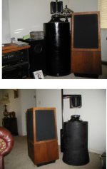
Attached you will notice the precision tilt mechanism employed - consisting of a couple of pieces of scrap MDF planks placed under one edge of the speaker. You may also notice the prototype precision externally mounted crossover network along with a bit of felt to cover the vent hole of the Pioneer speaker.
I call this speaker unit "Alpha" and it's mate "Beta" for good reason!
The finished units will be refined a tad - but I just love prototyping!
Thanks for the tip - more investigation to come!
BTW - these litter buggers are good enough to discern the microphone pattern used to record piano (near or far miked - single or multi miked) and I can hear the foot pedal work on the stops. On violin I can hear the individual strings played on chords. Not to bad!
I have followed your suggestion and with some degree of success!
I can discern an improvement from my sitting position but have not had the chance to sample my other listening post as the spousal unit is camped out in the reading chair spot and when reading enjoys the music at around 60 db - not my normal 90 db's! Provoking her in any manner could lead to a "I'm getting out of the house and going shopping" response as a passive-offensive counter maneuver on her part and is to be avoided. Further testing at my favored SPL's shall need to wait until Her Majesty relocates to the home office. A small price to pay - I assure you!
Attached you will notice the precision tilt mechanism employed - consisting of a couple of pieces of scrap MDF planks placed under one edge of the speaker. You may also notice the prototype precision externally mounted crossover network along with a bit of felt to cover the vent hole of the Pioneer speaker.
I call this speaker unit "Alpha" and it's mate "Beta" for good reason!
The finished units will be refined a tad - but I just love prototyping!
Thanks for the tip - more investigation to come!
BTW - these litter buggers are good enough to discern the microphone pattern used to record piano (near or far miked - single or multi miked) and I can hear the foot pedal work on the stops. On violin I can hear the individual strings played on chords. Not to bad!
Attachments
Thomas...
I passed an idea past Bud and he suggested that I post here for you to consider. This pertains to building a Walsh driver without a cone.
Walsh used a cone with a vertical axix which was driven from one end (I don't think it matters which end) the voice coil induced a shock or ripple wave that moved through the length of the cone. this wave or ripple coupled with the air arround the cone and generated an expanding cylinderical wave front in the surrounding air at more or less right angles to the cone. The same thing can be achieved without using a cone at all.
Replace the cone with a platic film (horizontal), the voice coil pulses the film and launches a forward wave front in the air the same size as the coil. At the same time a traveling wave is launched into the film (radial expanding traveling wave) and if the wavefront in the air and the wavefront in the film are similar in speed of transmission, then the lewading edge of the wave in the film will spread or expand the trailing edge of the wavefront in the air. The result is half of a hemisphere wave in the air. As a dipole you will achieve a hemispherical wave in the air.
I like to think of this idea as a hornless horn loaded loudspeaker. The film provides a medium for the expanding traveling wave which acts as a horn waveguide would do without the physical necessity of the physical horn.
You can have a look at the Highwood Audio patent US# 4 924 504. Let me know what you think. Regards Moray James.
Hi Moray,
I wonder what would happen if you connected a true Walsh profile, self supporting cone, out of a material similar to the flat panel, to the voice coil and positioned a globe or some more useful shape above the cone center to redirect and phase change that information. We could put a spider at the bottom of the voice coil to support the Walsh cone if needed. Would we get three frequency bands being emitted into a tubular pattern? Seems like everything would be coherent in phase, extremely transparent and dynamic. hmmmmmmm
I think we can expect to see C2C jump on your idea pretty soon. He always likes to push ideas around.
Bud
well you could do that....
the material that we used was 150 gage biaxially oriented mylar film. So if you made a cone out of thicker mylar you would be trading mechanical structrual resonances in the cone itself where as we went for controlling tympanic resonances in a thin film. Which I thought would be easier but what do I know? With the film you dont need a cone to radiate off of you simply use the film to run the wave through and presto bingo you have a wavefront translated into the air itself.
A simple easy to do experiment for those interested would be to take a tweeter and remove the dome with a good sharp exacto knife and replace it with a tall pointy cione made from paper you would probably need some kind of reasonable termination at the apex say a pad of dense foam and there you go.
I don't really think that it matter which way around you make a Walsh driver in that you can drive the cone from the apex of the cone or you can drive it (the cone) from the outter edge. I vote for the outer edge as the whole structure will be more stable that way. You could fix the apex termination off of a stud mounted to the pole piece inside of the cone. That's what the German guys do with the Radial driver and it works for them. In fact if you used a plastic cone material that you could flex so that the apex of the cone turned inside out into itself then the tip could be hard mounted to the stud I just mentioned and the roll over could be used as your top suspendion/termination. I like that idea better than the barrel staves as in the German design. Simple and easy to make if you think about it.
I guess that we may be loosing some people here but it is really straight ahead. This leads into one of those areas that if you have to ask you probably should not do it. But you don't really have to understand everything to try it. Building up ideas like this does not cost much and you will learn more from any mistakes that you may make thanl by reading a book about it.
Our full range drive had a total moving mass (coil, former, tinsil leads and dust cap) all up of about a gram and a half. A mid or tweeter unit would be far less. At a gram and a half (full range)we were able to squeeze out a true 87 db efficiency so smaller units would be a lot heigher especially with neo magnets. Then you add the Enable and felt ideas and you are off to the races. Lets go from here and see what happens. Best regards Moray James.
Right now I'm thinking about a 3 dimensional variable density molecularly linked edge termination material - similar to the different size of air bubbles in the foam on a good head of stout where the size of the bubbles vary from small to large as they are farther away from the surface of the beverage. The 3D part comes into play at the edge of where the primary membrane material (in this case Mylar) begins to interface with the speaker surround and the very first transition from being a dense and uniform material begins its transformation to a dense open cell structure (about an inch or so away from the supporting frame). The transformation of the membrane material continues from dense to less dense (expanded size of cells) as the material gets closer to the supporting frame.
The frame of course is another problem to face - wither circular or square. Purely symmetrical frame dimensions present the highest reflection of the acoustic wave traveling along the speaker membrane and should be avoided either by altering the shape of the frame or membrane. Manger does an "angular" 9 pointed quasi "star" shape on their transducer as an example of what I am attempting to illustrate here. Other shapes would work as well - such as a nonlinear swerving type of pattern similar to the tracks left in the snow from slalom skiers. With square transducers 90 degree corners should be avoided and a multi-segmented arrangement of angles used (perhaps swerving) used to reduce the "corner trap" reflections. An unequal trapezoid shape comes to mind here.
Treatments with patterns such as BudP's EnABL that trap the acoustic wave traveling along the surface of the membrane and prevent or greatly reduce reflections from the frame or speaker surround would be very desirable and could perhaps even be a deposited "hard shell" thin film metal or plastic material.
With large flexible membranes the proper amount of surface tension is always a problem due to the expansion and / or shrinkage due to temperature and humidity or just plain old stretching of the material from use. Anyone that has seen a drummer "tune" his kit, or a "strings" player tune their instrument, knows what I'm talking about here.
Moray James and company may of resolved this issue of large membrane surface tension with the design of a surface wave planar transducer in patent 4924504 where a true "surface wave" travels across the membrane rather than the membrane moving in a pistonic manner usually found in most audio speakers. Although tensioning of the membrane is used in the device it seems to be much less when compared to an electrostatic speaker membrane and thus should be less susceptible to tension requirements or variations. Now if we get away from using the square frame described in the patent, use a little BudP EnABL, and toss in my thoughts on a 3 dimensional variable density molecularly linked edge termination material we might have something going here.
Of course you might need to offer some evening classes in geometry and physics to explain to your customers just what in the blazes is going on with their speakers!
BTW - the photo is of me with my trusty side kick Manfred the Wonder Dog. Anyone who knows me gets to know Manfred. The little aluminum beanie I'm wearing is a whole other story.
Attachments
feedback...
on the 3D edge termination it would seem to me that you would want to use a reverse structure with the largest bubble on the inside of the diaphragm and the smallest bubble structure at the edge of the diaphragm where it meets the frame. That way both the stiffness and density of the suspension increase as it progresses to termination in the frame which is bound to be a high density/stiffness structure.
Regarding frame shape I was not worried about absolute at this stage of the game and I can tell you that if excuited well square or rectangular is not so very bad. I had figures a stop sign would work as the waves would get the message looking at the shape (ha).
One solution to termination which goes a long way toward your 3D idea but is far easier to do is to make a two part diaphragm. The inside (and bulk) of the diaphragm would be mylar with a small outter most section of silk screen mesh (also mylar). The two materials are bonded with an overlap joint using gllass caulking. The bond line is very thin and very strong. The mesh provides a wack of loss just prior to termination at the frame. While a low tech idea it works very well and is consistant.
diaphragm tension is not really an issue with speakers like these. If you use a biaxially oriented filc (c grade and tensilized) and stretch the diaphragm to about 2% thats all she wrote and it wont change. This is not like those guys who drum with 16 ounce framming hammers. After almost 20 years experience with the Highwood/Sumo/Museatex speakers I don't have any concerns in that department at all. Regards Moray James.
Hi Moray,
Thank you for the feedback and your ideas as I truly appreciate input from pro's such as yourself and BudP, Lynn, Dave, Bob P, Ed and so many others. This sort of collaboration really keeps the old mental juices going - that's for sure!
The "bubbles" aren't bubbles but a solid gel sphere (on a microscopic scale) material similar to the gel that artificial fishing lures like the rubber worms are made from - jelly like in consistency - and thus mass would increase as one approached the edge terminus because there are more of them and they are larger in size.
I like your "mesh" idea and had been considering using a fiber material such as Acoustastuff combined with a binding agent to provide some elasticity but thought the soft rubber spheres would be more consistently applied. However the mesh idea does play with the frame - or surround - in that I have considered not using a traditional frame at all but simply allow the Mylar to hang like a sheet in the breeze with just a few strands of elastic bands to secure it to a support - trampoline like in concept - and even this "frame" could be made from a material that offered additional damping characteristics. The "mesh" idea reminds me of some feedback provided by Lynn O. where he mentioned actually drilling a pattern of holes in the cone material that graduated in size and were placed near the cone edge to function as a BudP EnABL pattern to dump off the acoustic wave traveling along the surface of the cone.
These approaches would take some R&D in that they could make for a very "dead" over damped speaker cone - whereas BudP's EnABL pattern seems to increase the cones output by forcing the "wave" to jump into the air because it doesn't have any where else to go and the energy of the incoming wave forces the reflected wave off the speaker surface (well - a little bit of both waves actually). This is similar in concept to two waves crashing against one another on a body of water.
The fact that diaphragm tension is not a major issue with this design is one of the aspects I very much like about it.
Hello Hartono - Welcome to out little party!
Your point about Mylar is well taken but best answered by James as the speaker was patented by his company - however I do have some thoughts along those lines myself. Why Mylar? There could be other materials to consider - but Mylar is a very light and strong material. So why not?
FFFeedback...
Hey Hartono: Biaxially oriented mylar film like this gets used for capacitors, micro switches audio and video tape backing and tons more. Has high strength is a strong dielectric, has excellent stretch qualities and is very stable so good for things like flexible circuit boards and the like.
C2CT I still can not wrap my head about your bubbles but for now I will take your word for the density increasing toward the frame edge.
Tighter diaphragm equals higher efficiency (greater restoring force) so a limp skin is going to sound that way. I like Lynns idea of the mesh frame stucturally rigid but lossy at the same time. I agree that Bud' s dots and the Mamboni felt would probably each help a lot and would be well worth the effort to figure out in an application like this. Regards Moray James.
Hi ped!
I have been busy with other projects (and having great FUN!!) so the Walsh 5 Remakes version 3 are on the back burner for a bit. This pause serves a couple things - Time to closely listen and time to carefully consider my next attempt at "tweaking" those babies just a little more!!
My latest thoughts have to do with the result of "tilting" the 28 inch tube in the hopes of getting a "fuller" sound when seated. They are very full sounding when standing - and that fullness diminished a bit when sitting. The "tilt" was suggested my Moray James and worked well - but it has left me with some questions in design refinement. Secondly I am tempted to try out the Pioneer 12 inch woofer that is similar to the 10 inch but doesn't go quite as high - it's 5Khz vs. 6Khz for the 10". By having used the 14 inch ID SonoTube I have some room to play with on the baffle and can easily fit the 12 inchers.
I have also been playing around with the idea of fabricating a taller paper cone to replace the standard one.
Now that presents some real problems with extending the basket assembly and screwing up the driver by overloading it - but what the heck - they only cost $45.00 so no real big deal with the expense - it's finding time that is the problem!!
Still - for the cost of these at around $400.00 for the pair (depending on the tweeters you select it could be less - or more) these guys are pretty hard to beat. I simply love the "open" sound they produce due to the speakers being out in the air and thus getting rid of many problems of enclosed speakers - and they have a very wide sound stage.
I'm sure that version 3 will go back to the 28 in tall by 14 inch ID SonoTube and have a tilt somewhere between 15 and 30 degrees.
Hope this helps - feel free to make suggestions or ask questions if I can be of assistance .
I have been busy with other projects (and having great FUN!!)
so the Walsh 5 Remakes version 3 are on the back burner for a bit. This pause serves a couple things - Time to closely listen and time to carefully consider my next attempt at "tweaking" those babies just a little more!! My latest thoughts have to do with the result of "tilting" the 28 inch tube in the hopes of getting a "fuller" sound when seated. They are very full sounding when standing - and that fullness diminished a bit when sitting. The "tilt" was suggested my Moray James and worked well - but it has left me with some questions in design refinement. Secondly I am tempted to try out the Pioneer 12 inch woofer that is similar to the 10 inch but doesn't go quite as high - it's 5Khz vs. 6Khz for the 10". By having used the 14 inch ID SonoTube I have some room to play with on the baffle and can easily fit the 12 inchers.
I have also been playing around with the idea of fabricating a taller paper cone to replace the standard one.
Now that presents some real problems with extending the basket assembly and screwing up the driver by overloading it - but what the heck - they only cost $45.00 so no real big deal with the expense - it's finding time that is the problem!!
Still - for the cost of these at around $400.00 for the pair (depending on the tweeters you select it could be less - or more) these guys are pretty hard to beat. I simply love the "open" sound they produce due to the speakers being out in the air and thus getting rid of many problems of enclosed speakers - and they have a very wide sound stage.
I'm sure that version 3 will go back to the 28 in tall by 14 inch ID SonoTube and have a tilt somewhere between 15 and 30 degrees.
Hope this helps - feel free to make suggestions or ask questions if I can be of assistance .
You know c2thomas:
I admire your patience and methodical approach. When I was building these projects, I was so anxious to hear the effects of the cone mods that I literally affixed the drivers to the unfinished tubes with clamps, and attached the tweeters with tape and wired all with alligators. I was so thrilled with the resulting sound that I kept them running for days and was loathe to dismantle them and complete the finishing work.
Lately, I've been listening almost entirely to my Ohm Walsh 5 Series 3 pair in my study, driven by my Sumo Andromedas. Well, they are simply incredible loudspeakers - the initial thrill has not worn off 2 years later - rather, they seem to get better and better: the midrange microdynamics seem to improve weekly - or it's my imagination. What I have been preoccupied with is: how is John S. of Ohm Acoustics getting so much perfect bass out of these 12" woofers? I mean, the bass is just jaw dropping - and based on my TS calculations using some of the best woofers on the market in a 3 cu ft ported box, I can't replicate his achievement: in room ruler flat to 20 hz, probably 16 hz. I have a notion: I suspect that he has mass loaded his woofers to deliberately drop the Fs to 16 Hz while preserving Vas and Qts. Sure, efficiency suffers, but if one uses a powerful enough magnet and a light cone, one can achieve a reasonable efficiency with truly wideband response. After all, the upper cutoff is limited by the voice coil mass and inductance. The Pioneer 12" you mention is very efficient - mass loading could drop the Fs substantially and still retain sufficient efficiency and outstanding bandwidth - I believe useful response to 6-8 kHz is quite doable.
Hi mamboni!
Good to see you around looking in on things! It's my nature to keep wringing sponges until every last drop is out - sometimes I wind up with two sponges tho
Part of me wants to keep wringing out "just a little" more from the tubes - knowing full well that there can't be to much more to get out! Great speaker project for a newbie such as myself with great cost to benefit ratio and a fairly easy build. My wifes son (different father) is up visiting this week and we plugged in some of his DVD's and cranked up the VOLUME in HT mode. The room was shaking and the windows were rattling and everything was just so great to listen to. The wide sound stage works very well for Home Theater! But I like to listen to them in stereo with a touch of sub-woofer to fill out the low end. Often I will have them turned up so I can hear them playing from my home office and something will come on that I want to listen to and I'll wonder out to the living room and forget to come back. I haven't just sat and listened to music - and I do mean listen with enjoyment - in such a long - long time. I have listened to "stuff" for a long time - now I'm enjoying music. Big Difference. And these speakers are just the start of my system. Looking at the rest of the string now.
Thank you mamboni for your design! I'm loving mine! But you just know that I'm gonna get in there and mess around with things! I can feel some 12 inch Pioneers coming soon!
Why? Cause I can!!
Good to see you around looking in on things! It's my nature to keep wringing sponges until every last drop is out - sometimes I wind up with two sponges tho
Part of me wants to keep wringing out "just a little" more from the tubes - knowing full well that there can't be to much more to get out! Great speaker project for a newbie such as myself with great cost to benefit ratio and a fairly easy build. My wifes son (different father) is up visiting this week and we plugged in some of his DVD's and cranked up the VOLUME in HT mode. The room was shaking and the windows were rattling and everything was just so great to listen to. The wide sound stage works very well for Home Theater! But I like to listen to them in stereo with a touch of sub-woofer to fill out the low end. Often I will have them turned up so I can hear them playing from my home office and something will come on that I want to listen to and I'll wonder out to the living room and forget to come back. I haven't just sat and listened to music - and I do mean listen with enjoyment - in such a long - long time. I have listened to "stuff" for a long time - now I'm enjoying music. Big Difference. And these speakers are just the start of my system. Looking at the rest of the string now.
Thank you mamboni for your design! I'm loving mine! But you just know that I'm gonna get in there and mess around with things!
I can feel some 12 inch Pioneers coming soon! Why? Cause I can!!
Mamboni....
why don't you have a look see inside and find out why the Walsh bass sounds so good and then give us your assesment?
Thomas it would seem to me that before you jump ship to the 12 inch drivers you might want to do some surgery on the 10 inch units. I would suggest that you replace the the stamped steel basket legs for some 3/8 inch cold rolled steel struts. You could add a couple of extra struts and have a far more rigid motor mount than the factory basket flanges provide. They could be mounted with some structural epoxy glue and when cured take the tin snips to the factory flanges and while you are there roll back any flange at the edge of the spider so the air flows in and out over a smooth shoulder rather than a sharp edge. The amount of reflected/defracted sound there is off of the stock basket legs is huge so why not just make it go away? Regards Moray James.
- Home
- Loudspeakers
- Multi-Way
- OHM Acoustics "Walsh F" Speaker remakes