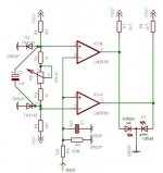
moamps said:Dual LED offset indicator
+ offset red
- offset green
zero orange
set window with R9
Regards
That's the idea, but I think in your circuit the window is always +/- .6V, independent of the pot. That's a pretty wide window for offset. I think that if you want to make the window variable (although I see no need for it), you need two pots, each across the diode and feed the fractional diode voltage to the comparator inputs.
You may also want to add a small positive feedback across the comparator to introduce some hysteresis, to avoid oscillations around the switching point.
You may also want to put R7, R9 in series with the comparator outputs to limit the LED current.
Lastly, place diodes across the LEDs in opposite polarity to avoid destroying them with too much reverse voltage.
Jan Didden
boholm said:I would prefer the LED not to light at all, when there is no DC. That's more logical to me. Agree or disagree?
Agree
Circlotron said:If you need an indicator to tell you that you have offset because you cannot hear it...
haha... somebody found out the secret!
Hi Jan,
thanks for yours correction.
Drawing error. Corrected.
Two pots aren't needed if window is symetrical.
Done.
Regards
thanks for yours correction.
janneman said:That's the idea, but I think in your circuit the window is always +/- .6V, independent of the pot.
Drawing error. Corrected.
....you need two pots, each across the diode and feed the fractional diode voltage to the comparator inputs.
Two pots aren't needed if window is symetrical.
OK, but not so important.You may also want to add a small positive feedback across the comparator to introduce some hysteresis, to avoid oscillations around the switching point.[/B]
Led current is defined only with R7 and R9. In corrected schematic with R7+R10 and R9+R11.You may also want to put R7, R9 in series with the comparator outputs to limit the LED current.
Lastly, place diodes across the LEDs in opposite polarity to avoid destroying them with too much reverse voltage.
Done.
Regards
Attachments
I'm sorry, but this won't work (I might be wrong).
1 LP-filter, preferable up to 3th or even 4th order, cut frequency 0.01-1 Hz. Those filters most also have low offset voltages. This is dependent how low DC voltage you want to detect, how advanced the filter should be.
2 Fullwave rectifier or two halfway rectifiers, one for positive and one for negative signals
3 Comparator with HYSTERESES!
4 Indicators
Filtering out a couple of millivolts from several volts or tenths of volts is a tricky business. Don't forget that DC is low frequency AC!
Hi,peranders said:I'm sorry, but this won't work (I might be wrong).
I have this on breadboard. Works reasonably good.
Too complex.1 LP-filter, preferable up to 3th or even 4th order, cut frequency 0.01-1 Hz. Those filters most also have low offset voltages. This is dependent how low DC voltage you want to detect, how advanced the filter should be.
Too many additional IC's.Fullwave rectifier or two halfway rectifiers, one for positive and one for negative signals
...will destroy windows margine.3 Comparator with HYSTERESES!
Filtering out a couple of millivolts from several volts or tenths of volts is a tricky business. Don't forget that DC is low frequency AC!
What about simple (one IC) DC servos in amps? Doesn't look so tricky.
Regards
OK, but even so the integrator must be extremely slow and/or you need extra filters.janneman said:Per-anders,
You may remember that this comparator stuff is preceded by an integrator like the servo loop normally used to null the offset. Please look up the previous posts.
Jan Didden
peranders said:
OK, but even so the integrator must be extremely slow and/or you need extra filters.
Not different from 'normal' servo loops. The fact that they are used in many 10.000's of amps is some indication that most probably it works. I concede that often the implementation isn't very good, but we have beaten that particular horse to death in this thread I would think.
Jan Didden
peranders said:OK, I'll back off a little but if you take signal from the DC servo intergrator you will not get an exact measure of the offset. The servo output is only a signal inside a feedback loop and tell you not much really.
You obviously have not taken my advice to read the former posts. The servo loop is not closed, because he wants to regulate the offset by hand. I said "an integrator LIKE the servo loop NORMALLY used to....". There is no closed servo loop and the integrator output is the offset voltage, at least above the low pass freq. And indeed that should be low enough so that there is no lf audio to slowly vary the apparent offset.
Can I go now?
Jan Didden
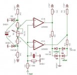
Here's some initial doodlings of my linear idea
This is meant to be implemented with a quad op amp. The first section is a differential integrator which will probably change - I drew it this way because I wanted to be able to select this circuit as a bias monitor as well as a offset monitor circuit. The second and third op amp sections and associated components comprise a high speed 'ideal' full wave rectifier. The final op amp stage acts as a bipolar current source to linearly control the LEDs intensity. 'Off' would correspond to 0 volts offset, in this case. I threw in D5 and R16 to limit sensitivity more than several tenths of to a couple volts away from the null range. All component values hypothetical
This is meant to be implemented with a quad op amp. The first section is a differential integrator which will probably change - I drew it this way because I wanted to be able to select this circuit as a bias monitor as well as a offset monitor circuit. The second and third op amp sections and associated components comprise a high speed 'ideal' full wave rectifier. The final op amp stage acts as a bipolar current source to linearly control the LEDs intensity. 'Off' would correspond to 0 volts offset, in this case. I threw in D5 and R16 to limit sensitivity more than several tenths of to a couple volts away from the null range. All component values hypothetical
Attachments


- Status
- This old topic is closed. If you want to reopen this topic, contact a moderator using the "Report Post" button.
- Home
- Amplifiers
- Solid State
- Offset Voltage Indicator?