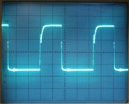
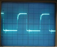
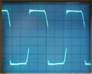
Looks pretty good to me. To be picky you could work on the bus impedance to try to get rid of the minor ringing on turn-on.
And also.. That spike that you see when the other IGBT turns on is just a common mode noise. It's normal. The IGBT does not 'see' this. To verify this you can take the scope and place the tip on the emitter of the lower IGBT and place the ground at the same point. You will see the same spikes. You can also put a ground eliminator tip on the probe which reduces the probe ground to under 0.5". The spikes will be deminished greatly.
Most likely you do not need this new gate drive circuit but it would be interesting to see if there are efficiency improvements. Did the previous gate drive waveshapes look similar? Also I usually place a loop in the the connection on the drain or collector and insert a current probe to check out the actual transistor current to see if there is anything funky going on.
Workhorse: (or anybody else):
I have studied the QSC patent, but I don't understand it.
They claim that their power supply maintains resonant operation thoughout all combinations of loading of the amplifier.
When I measure my transformer I get a leakage inductance of about 1uH (secondary shorted) and a total primary inductance of about 1mH (secondary open). I assume that the QSC transformer is similar.
When I do a PSpice simulation of the supply with a primary series capacitor of 1uF with the supply unloaded (no signal to the amplifier), the resonator resonates at 5kHz. Only untill I load the supply with over a kiloWatt the resonating frequency shifts towards 100kHz.
So, it seems to me that the supply does not resonate when it is lightly loaded?
Can anybody explain?
fortissimo68 said:Workhorse
So, it seems to me that the supply does not resonate when it is lightly loaded?
Thats what i told you earlier, that with 1uF cap resonance at lighter load is very difficult to obtain........
QSC smps behave like normal type when subjected to lighter loads or open loads, resonance only kicks in when the primary current exceeds 800mA......
The transformer is foil wound with 2 X 14 turns on Primary side....
Why dont you decrease the cap value to .47uFD??
So, I guess that what the QSC patent is about, does not work. (That the power supply maintains resonant operation thoughout all(!) combinations of loading of the amplifier, as stated in the patent).
I will experiment with the capacitor. But i think that lowering it will increase the voltage on the capacitor and thus will give more dumping of the secondary voltages?
I will experiment with the capacitor. But i think that lowering it will increase the voltage on the capacitor and thus will give more dumping of the secondary voltages?
I did find that you can add a resonant tank circuit on the secondary side if you really want to maintain ZVS at light loads. You're welcome to rummage through my experimental circuits on my group Web-site. They are done in LTspice, so you can simulate them to observe how it works and various component changes affects things. The group is members only for various reasons, though.
fortissimo68 said:I think I need ZCS, not ZVS.
How do I create a resonant tank on the secondary side? Do I just add inductors after the rectifiers?
It involves using an inductance in series with the transformer secondary, and a capacitor going after that inductor to ground. You may then need at least one diode to shunt resonant peaks to either the output capacitor or to ground.
ZCS is hard to implement in its pure state, I have found. You'd either have to use frequency modulation of the circuit, or regulate it with a magnetic amplifier, though I've read it is not hard to do, seems easier said than done for complete regulation from no load to maximum, especially for a single output supply.
I seem to have found that the results from trying to have a tank circuit able to maintain ZVS at no load using just the primary side just are not as good. It seems to be because the leakage inductance of the transformer adds in a bigger benefit in the process when the secondary side is used.
- Status
- This old topic is closed. If you want to reopen this topic, contact a moderator using the "Report Post" button.
- Home
- Amplifiers
- Power Supplies
- Offline halfbridge smps gate drive