
 , and 1mA is going from + to TL
Connections
Luka
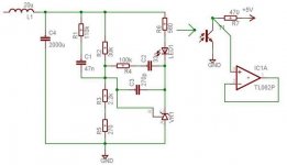
Refer to pg#180-184 in Brown's book "Power Supply CookBook" the circuit is explained in detail,check all your connections. The value for the bais resistor for the Tl431 seems low to me should only allow about 10 ma . I need to check the data sheet for the
Tl431, 35 volts might be high for proper operation.
chas1
Luka
Refer to pg#180-184 in Brown's book "Power Supply CookBook" the circuit is explained in detail,check all your connections. The value for the bais resistor for the Tl431 seems low to me should only allow about 10 ma . I need to check the data sheet for the
Tl431, 35 volts might be high for proper operation.
chas1
 to all.
feedback
Luka
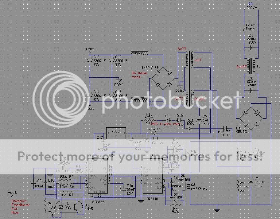
If you like you can breadboard this circuit and verify it will work with your design, the component calculations should be based on your gain requirements at the crossover frequency you choose. I don't understand why you have so much capacitance on your output rails it only complicates the feedback design I think two 1000 uF caps in each rail should be ok and then I would add .1 ohm resistor's in series with them and you could increase your crossover frequency with ease. With your current design I would cross at no higher that 5 kHz.
chas1
Luka
If you like you can breadboard this circuit and verify it will work with your design, the component calculations should be based on your gain requirements at the crossover frequency you choose. I don't understand why you have so much capacitance on your output rails it only complicates the feedback design I think two 1000 uF caps in each rail should be ok and then I would add .1 ohm resistor's in series with them and you could increase your crossover frequency with ease. With your current design I would cross at no higher that 5 kHz.
chas1
Attachments

- Home
- Amplifiers
- Power Supplies
- Offline full-bridge SMPS… need help