
Perfect, will do Zen Mod -
The FAT C situation may be the deal breaker with these. Spec calls for 3000uF max. I have wondered about using a soft start to mitigate inrush and going for broke with C. Or maybe there are other reasons that will make these ring aside from startup.
Also looking at the 700mv PP ripple lol! That's really bad; usually 200 PP seems to be the standard, Meanwell bricks included. I did manage to find a TDK version that claims 28mV PP and 10000uF max C. So If I can make these ABBs work then the TDKs will be the go to in future.
The power supply in one of my Class A amps is a pair of MeanWells each with a capacitance multiplier board at the output, then wired in series for a bipolar psu.
The cap multiplier boards reduce the SMPS ripple to a very low level and act as a "softstart" so additional capacitors do not cause the SMPS's to enter hiccup mode at startup.
The cap multiplier boards reduce the SMPS ripple to a very low level and act as a "softstart" so additional capacitors do not cause the SMPS's to enter hiccup mode at startup.
Hmm, when I connect the 'center tap' one side drops out and I get 0/0/24. Having tried multiple combos nothing will create the reference point to get both polarities relative to a single point. Whatever it's doing, it's not behaving the same as when I use a center tap on a series string of batteries. And from the description of the Meanwell connection, that is exactly the same connection strategy as the series battery. Maybe Christmas 2.0 is dashed...
Edit: These converters are non-isolated. I'm starting to come across info about this and it sounds like isolation is a prerequisite.

Edit: These converters are non-isolated. I'm starting to come across info about this and it sounds like isolation is a prerequisite.
Last edited:
following with interest...
I have an M2X with NP original front end buffer, I have 4x LRS 100-24 SMPS to yield bipolar supplies wired as two independent pairs. I am using the V+ and V- outputs to generate +24, -24 and 0 as post #3634. V+, V- and "0" go straight to the M2X boards. The L,N & Gnd on the input side of the LRS SMPS are connected back to the mains input and ground tied to the chassis.
I have a minor 50Hz(?) hum that can be heard close to the speakers. To track down the hum I have shorted the RCA inputs to the board o/p GND and they are isolated from the chassis ground. There is 10ohm in the signal return.
Skylar did you test your system with the SMPS near to the amplifier boards? - I wonder if I have noise from a wiring issue, or whether its pickup via the autoformer and one can only achieve near silence by remote mounting the SMPS or shielding the Edcor...
No, I haven't tried putting the SMPS inside the case near the boards. You may have to extend the power leads and test that yourself. I vaguely remember XRK971 had the same issue and he eventually sorted it out and in his thorough style, documented the journey in this thread - or was it the M2X thread?
Last edited:
Largely resolved: copied here in case its useful anyone else...
Removed the 4 LRS-100-24 smps and placed 15ft away. Then fed the two independent supplies of +24,-24 &"0" via some thick mains cable direct to the boards. This cut the hum down dramatically but left a high pitched ticking /buzz that appeared on the tweeter. I then strung a safety ground from the PSU mains input to the amp chassis and this dropped the tweeter noise further still. With the inputs shorted there is still some minor buzz/ticking on the tweeter, but it's dramatically reduced from before. I will stick the supplies in a small Galaxy and see how that works out and maybe add Mark Johnsons smps filters.
Removed the 4 LRS-100-24 smps and placed 15ft away. Then fed the two independent supplies of +24,-24 &"0" via some thick mains cable direct to the boards. This cut the hum down dramatically but left a high pitched ticking /buzz that appeared on the tweeter. I then strung a safety ground from the PSU mains input to the amp chassis and this dropped the tweeter noise further still. With the inputs shorted there is still some minor buzz/ticking on the tweeter, but it's dramatically reduced from before. I will stick the supplies in a small Galaxy and see how that works out and maybe add Mark Johnsons smps filters.
I was playing around with a simple push pull circuit on LTspice, and eventually I could not but notice that 3 resistors in series for a floating bias arrangement look very much like a simplified M2. The resistors handle DC for biasing, and the cap gives a direct path for AC to both gates.
So what I was wondering is what is the purpose of the optocoupler biasing arrangement.
I remember reading something that it is to slowly turn on the mosfets to prevent turn-on thumps and prevent thermal runaway? But in true lazy/greedy boy fashion I am just asking instead of reading the entire thread from the start.
opto is giving you circuit with feedback, so active
3 resistors is passive solution, good only for parts without Temp. coefficient, and there are none
even lateral mosfets are having 0 TempCo around 100mA and after that, luckily, negative TempCo
there are several posts around explaining exactly bias mechanism of M2
you can start with post #2, here: https://www.diyaudio.com/community/threads/sissysit-r-3.371272/post-6626296
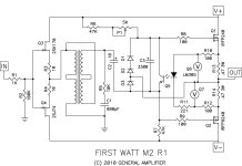
Going back 12 years or so, here is the schematic of the M2.
I thought the bias circuit was particularly clever. That circuit without the LM385 voltage references
will set up a constant bias via the opto isolator, but when the output current exceeds the Class A
region the bias tends to decrease because there is a net increase in the average DC across the
output Source resistors. The 385's limit the high transient across each resistor so that the DC
bias value is not affected. It does require careful adjustment in design, but not in production.
Attachments
Thank you both so much
So, the optocoupler's transistor acts like a variable resistor and biases the fets initially high as the capacitor fills with DC, and then slowly puts the breaks on them as the current on the led increases.
And the LM385s put a limit to that breaking so that it does not go too low
I was wondering (as I don't like unusual parts) if we could do something similar with a simple capacitance multiplier to act like a buffer between the voltage in the source resistors and the feedback to the biasing resistors/transistor. But I guess you cannot beat the simplicity of the isolation of the optocoupler when designing the balance point.
BTW, from the datasheet of the 4N35, its LED's forward voltage is 1.5V. Was that not enough to keep the voltage on the source resistors in check? I guess the voltage drop is not stable?
Last edited:
Sure, you can do anything you want! Douglas Self's power amp book shows his own implementation, which uses a bandgap reference IC instead of the input half of the optoisolator, and an operational amplifier IC instead of the output half. It's got a lot more components and, since it's a negative feedback control system with LOTS of gain, it also needs compensation circuitry to ensure it remains stable & doesn't oscillate. However Self's circuit does have the great advantage of NOT infringing upon Nelson Pass's patent on the optocoupler biasing idea (U.S. 4,752,745).
- Home
- Amplifiers
- Pass Labs
- Official M2 schematic